Clipper with locking device and detachable clipper head

A locking device and hair clipper technology, applied in metal processing and other directions, can solve the problems of unfavorable cleaning of hidden hair, complex structure, and many parts, and achieve the effects of avoiding removal or flying out, easy operation, and easy cleaning.

Active Publication Date: 2013-03-27
SPECIALIFE ZHUHAI
View PDF7 Cites 0 Cited by
  • Summary
  • Abstract
  • Description
  • Claims
  • Application Information

AI Technical Summary

Problems solved by technology

The other is to adopt the lock piece method, first press the unlocking button of the main part, open the lock piece, and then turn out the cutter head, this method is easy to make the lock piece return to the locked position, and needs to use tools to turn out the lock piece; this method has a complicated structure , too many parts; this method is also easy to hide hair and is not conducive to cleaning

Method used


Image

  • Clipper with locking device and detachable clipper head
  • Clipper with locking device and detachable clipper head
  • Clipper with locking device and detachable clipper head

Examples


Embodiment Construction

[0024] The specific implementation manner of the present invention will be further described below in conjunction with the accompanying drawings.

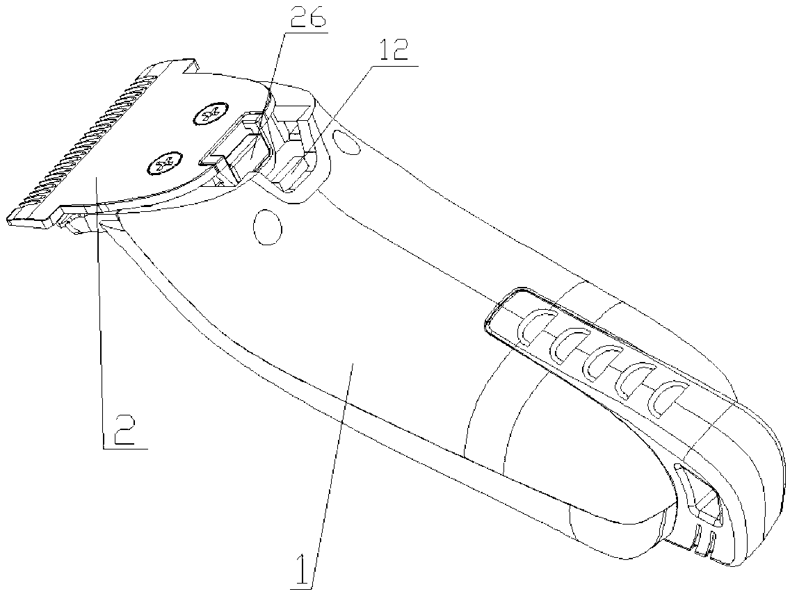
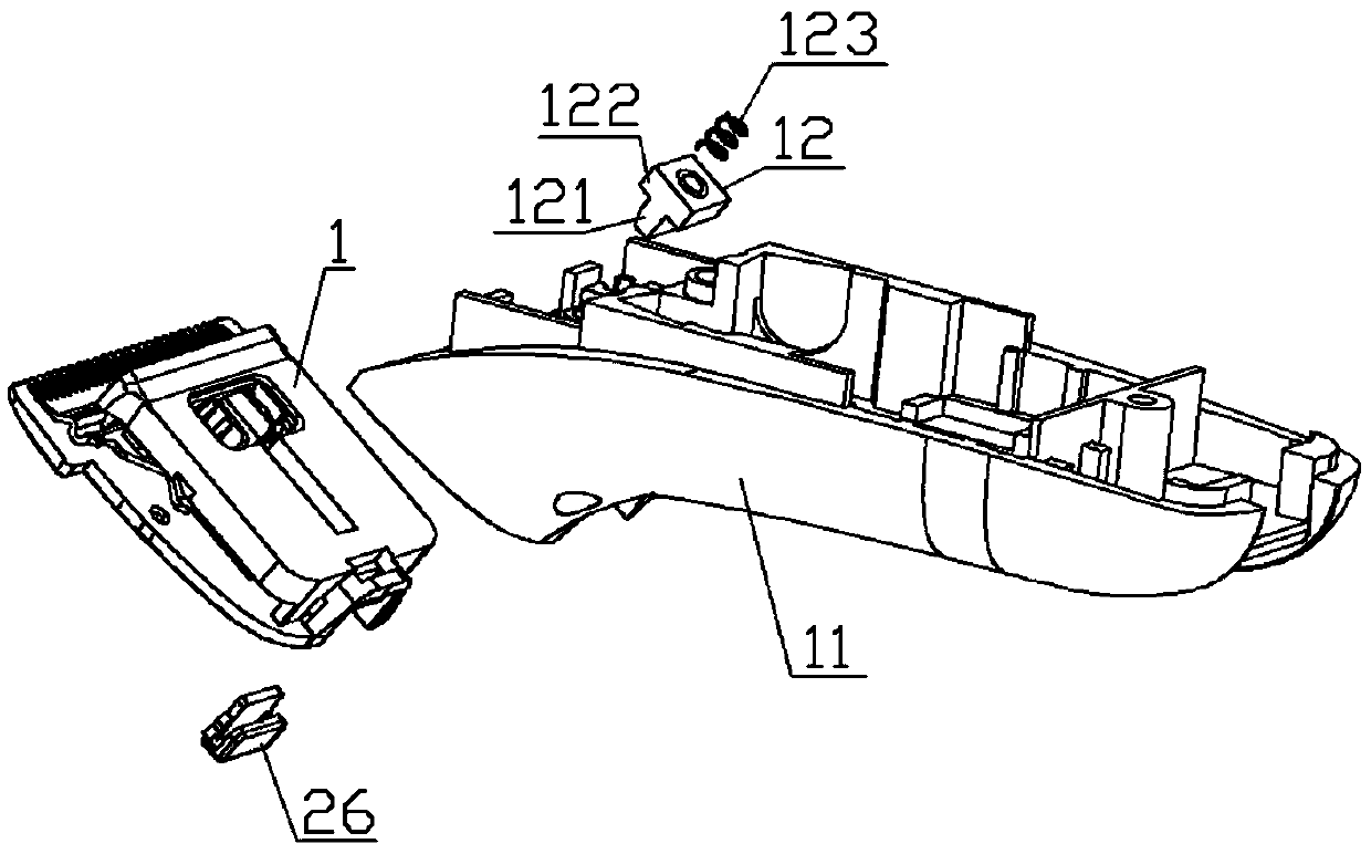
[0025] see Figure 1 to Figure 5 As shown in , the hair clipper with a detachable cutting head with a locking device in this embodiment includes a body 1 and a cutting head assembly 2 detachably connected to the end of the body 1 .

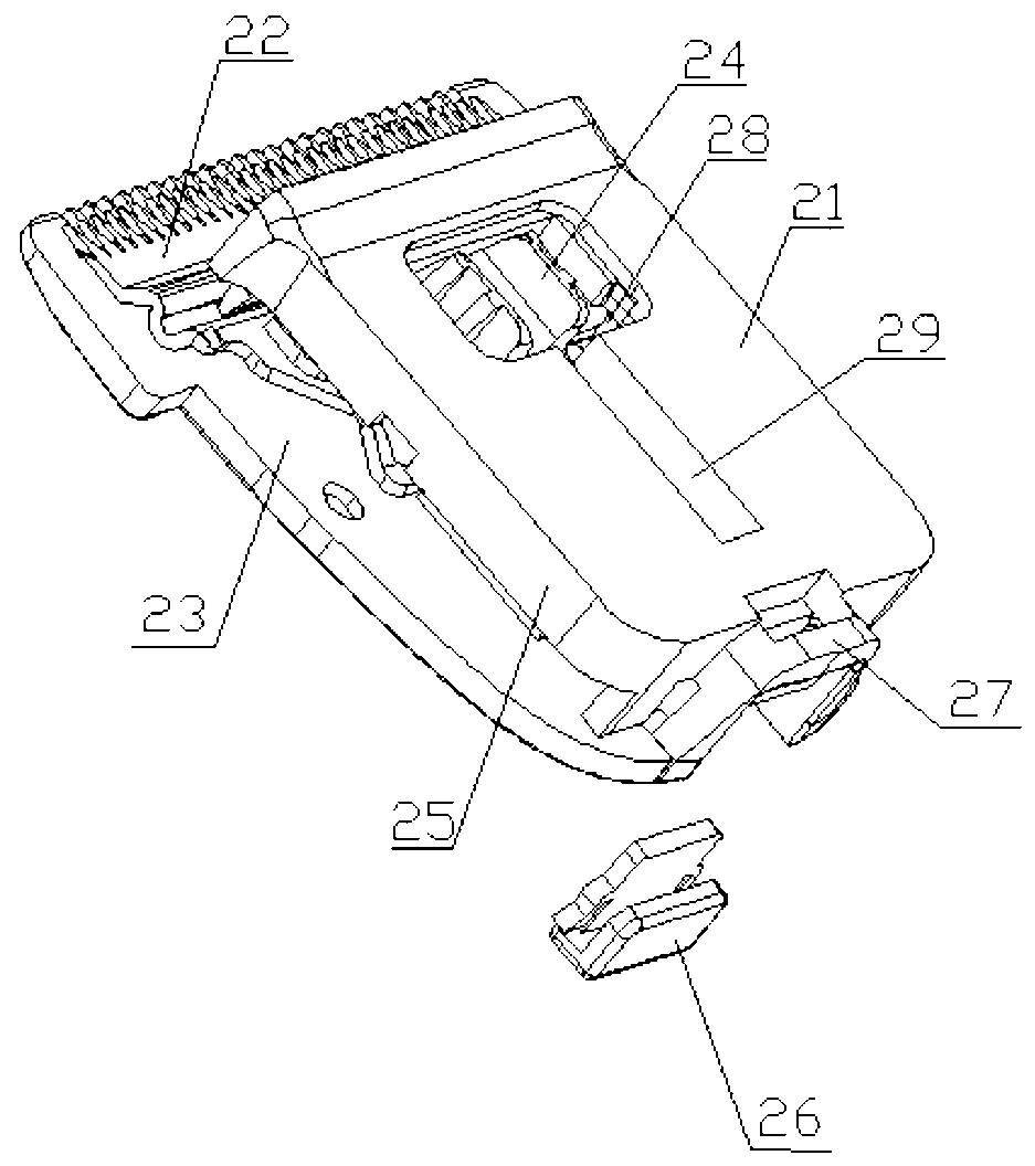
[0026] The cutter head assembly 2 comprises a cutter head support 21 with a cavity, a fixed blade 23 as the outer surface of the cutter head assembly 2 fixedly connected with the cutter head support 21, a movable blade 22 arranged in the cutter head support 21 cavity 1. A movable part 24 that is fixedly connected with the movable blade 22 and drives the movable blade 22 to reciprocate relative to the fixed blade 23; The edge of the knife tooth of the blade 23 is closely attached to form a shearing surface.

[0027] The end of the cutter head assembly 2 away from the shearing surface is provided with ...


PUM


Abstract

The invention provides a clipper with a locking device and a detachable clipper head. The clipper comprises a machine body and a clipper head component which is detachably connected with the end of the machine body, wherein the clipper head component comprises a clipper head bracket provided with a cavity, a fixed blade which is fixedly connected with the clipper head bracket and is used as the outer surface of the clipper head component, a movable blade which is arranged in the cavity of the clipper head bracket and a moving part which is fixedly connected with the movable blade and drives the movable blade to carry out reciprocating motion relative to the fixed blade, the fixed blade and the movable blade are respectively provided with a blade tooth edge, the blade tooth edge of the fixed blade and the blade tooth edge of the movable blade tightly cling to each other to form a shearing surface, a strip block is arranged at each of two opposite side edges of the clipper head bracket, a groove matched with each strip block is formed at each of the two inner sides at the end of the machine body, each strip block is arranged in each groove, and an elastic lock block is arranged at the end of the machine body and is used for locking the clipper head component. The clipper has a simple structure, is easy to operate, is high in safety and is very comfortable in usage experience.

Description

technical field [0001] The invention relates to a hairdressing appliance, in particular to a novel hair scissor with a detachable cutting head provided with a locking device. Background technique [0002] When cutting hair or shearing hair, the cutter head part of the hair scissors is easy to retain broken hair, so the cutter head part needs to be disassembled frequently for cleaning. When the existing hair scissors remove the cutter head, it is necessary to press the cutter teeth on the cutter head with fingers to remove the cutter. In this way, the fingers are easily scratched by the cutter teeth. The other is to adopt the lock piece method, first press the unlocking button of the main part, open the lock piece, and then turn out the cutter head, this method is easy to make the lock piece return to the locked position, and needs to use tools to turn out the lock piece; this method has a complicated structure , There are too many parts; this method is also easy to hide hai...

Claims


Application Information

Patent Timeline
Patent Type & Authority Applications(China)
IPC IPC(8): B26B19/06
Inventor 刘东欣
Owner SPECIALIFE ZHUHAI
Why Eureka
Try Eureka