
Lifting conveying device

A technology for lifting conveying and conveying devices, applied in the direction of conveyor objects, transportation and packaging, supporting frames, etc., can solve the problems of inflexible use of conveying devices, and achieve the effect of simple structure, convenient operation and flexible use

Inactive Publication Date: 2013-03-13
WUXI JIESI LOGISTICS EQUIP
View PDF0 Cites 2 Cited by
  • Summary
  • Abstract
  • Description
  • Claims
  • Application Information

AI Technical Summary

Problems solved by technology

[0003] Aiming at the shortcomings of the inflexible use of the conveying device in the above-mentioned existing production technology, the applicant provides a liftable conveying device with a reasonable structure, so that the height and position of the conveying device can be adjusted according to different application occasions, and the use is flexible and the application widely

Method used


Image

  • Lifting conveying device

Examples


Embodiment Construction

[0013] The specific implementation manner of the present invention will be described below in conjunction with the accompanying drawings.

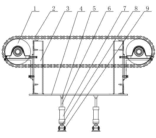
[0014] Such as figure 1 As shown, the liftable conveying device of this embodiment includes a conveying device, and the conveying device is installed on a base 4, and supports 3 are installed at intervals on the base 4, and supports are respectively extended at one end of the supports 3, and sprockets are supported on the supports. 1. The chain 2 is installed on the two sprockets 1. The lower part of the base 4 is provided with a lifting mechanism. The structure of the lifting mechanism is as follows: a fixed frame 9 is installed on the fixed frame 9 through the second bolt 8. The cylinder 7 and the piston of the cylinder 7 The head of the rod 6 is fastened to the base 4 by the first bolt 5 .

[0015] In this embodiment, two elevating mechanisms are arranged on the lower part of the base 4 in parallel and at intervals.

[0016] In actual...


PUM


Abstract

The invention relates to a lifting conveying device which comprises a conveying device part, wherein the conveying device part is mounted on a base; brackets are mounted on the base at intervals; a support is extends from one end of each bracket; chain wheels are mounted on the supports in a bracing manner; a chain is mounted on the two chain wheels; lifting mechanisms are arranged at the lower part of the base; the lifting mechanisms comprise fixing frames; air cylinders are mounted on the fixing frames by second bolts; and heads of piston rods of the air cylinders are fastened with the base by first bolts. The lifting conveying device is simple in structure and convenient to operate; the air cylinders act to control ascending and descending of the base effectively by controlling the ascending and descending of the piston rods; the base can drive the whole conveying device to change in the height direction; the device is flexible to use, low in cost and reliable to use; and the position of the conveying device can be adjusted conveniently according to different use requirements.

Description

technical field [0001] The invention relates to conveying equipment, in particular to a liftable conveying device. Background technique [0002] Conveying devices are widely used in logistics and transportation equipment. Most of the conveying devices in the prior art adopt fixed mechanisms. The conveying devices cannot be moved, and their use is not flexible. When the conveying device transports goods, it needs to be adjusted according to the needs of the site and the size of the space. The position of the conveying device, while the conveying device of the fixed mechanism cannot be adjusted, that is, the goods that can be conveyed are limited. Contents of the invention [0003] Aiming at the shortcomings of the inflexible use of the conveying device in the above-mentioned existing production technology, the applicant provides a liftable conveying device with a reasonable structure, so that the height and position of the conveying device can be adjusted according to diffe...

Claims


Application Information

Patent Timeline
Patent Type & Authority Applications(China)
IPC IPC(8): B65G41/00
Inventor 王建兵
Owner WUXI JIESI LOGISTICS EQUIP
Learn More