
Near eye tool for refractive assessment

An eye, optical system technology used in the field of vision meters and the evaluation of refractive disorders, which can solve problems such as increased pressure and headaches

Inactive Publication Date: 2013-02-27
MASSACHUSETTS INST OF TECH
View PDF0 Cites 28 Cited by
  • Summary
  • Abstract
  • Description
  • Claims
  • Application Information

AI Technical Summary

Problems solved by technology

However, this increases stress and headaches over time because they put in the extra effort to focus at infinity

Method used


Image

  • Near eye tool for refractive assessment
  • Near eye tool for refractive assessment
  • Near eye tool for refractive assessment

Examples


Embodiment Construction

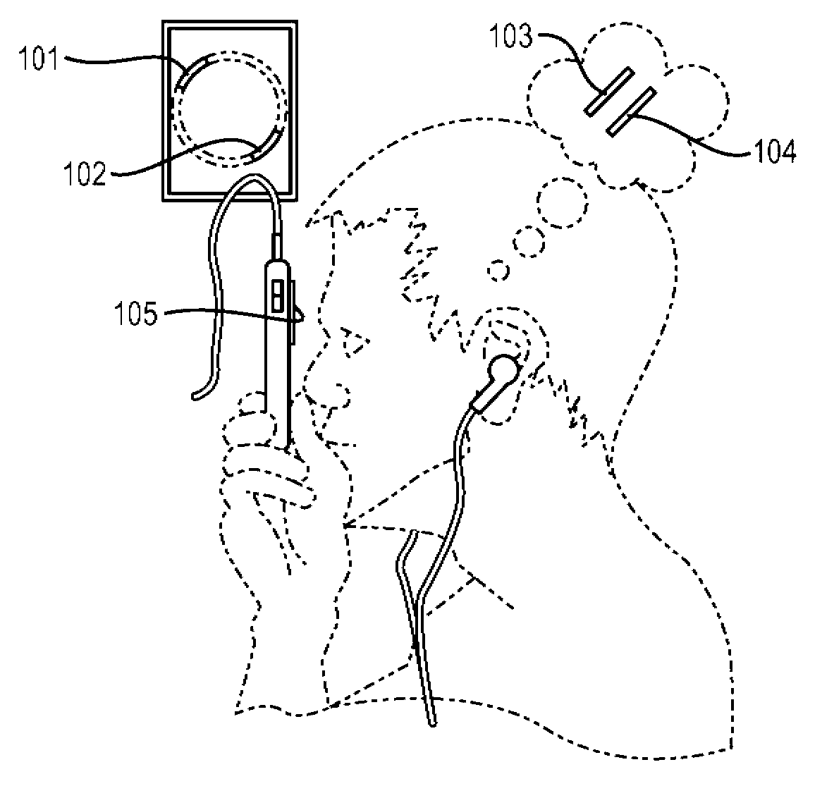
[0056] figure 1 A user is shown holding a smartphone to one of their eyes in an example embodiment of this invention. The LCD display of the smartphone is covered by a microlens array 105 . The LCD displays a green line 101 and a red line 102 . The positions of the lines thus displayed are pre-warped to correct (at least in part) lens aberrations of the eye. To the user, lines 101 and 102 appear as green line 104 and red line 103, respectively.

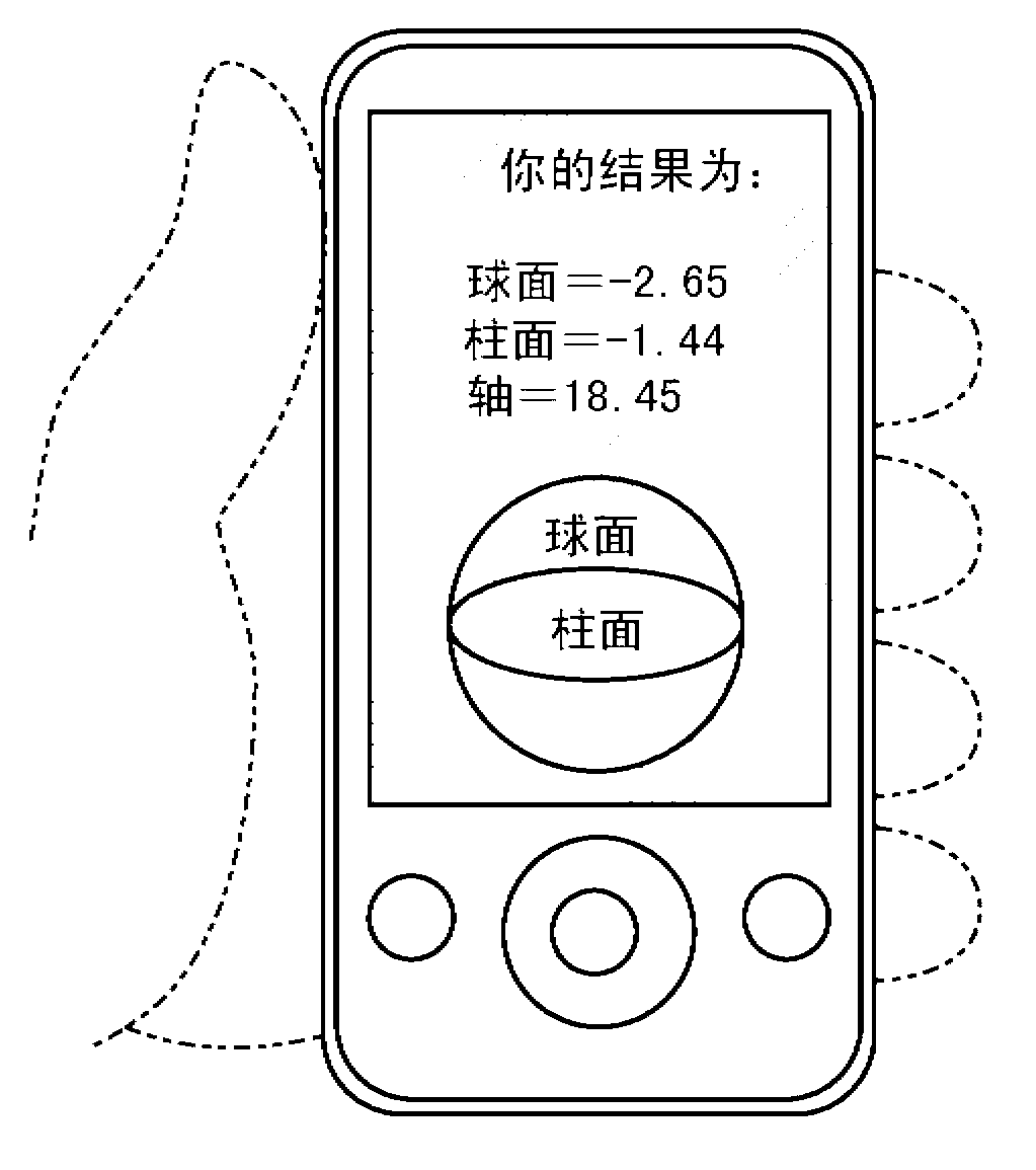
[0057] figure 2 Shown is a smartphone screen displaying the results of an assessment of visual acuity in an example embodiment of this invention. The results shown are the standard parameters used for lens prescriptions, namely (from top to bottom of the display) spherical power, cylindrical power, and cylinder axis. Other results can be displayed. For example, the screen may also display results for presbyopia, such as "Presbyopia: +3.00".

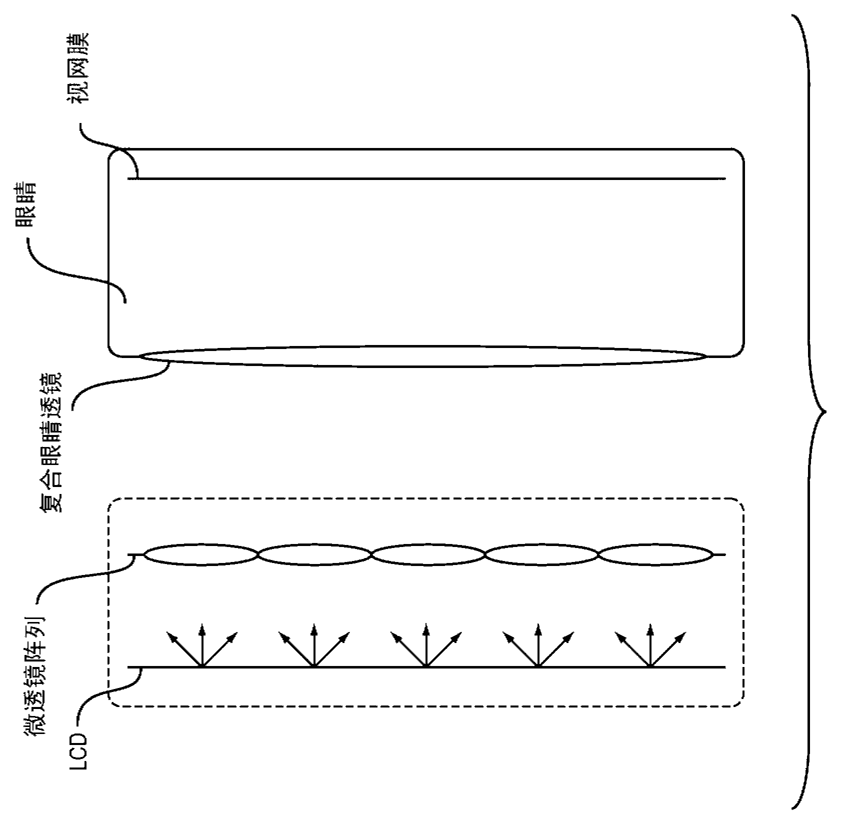
[0058] image 3 is a diagram showing a microlens array placed over a controllable hi...


PUM


Abstract

In exemplary implementations, this invention is a tool for subjective assessment of the visual acuity of a human eye. A microlens or pinhole array is placed over a high- resolution display. The eye is brought very near to the device. Patterns are displayed on the screen under some of the lenslets or pinholes. Using interactive software, a user causes the patterns that the eye sees to appear to be aligned. The software allows the user to move the apparent position of the patterns. This apparent motion is achieved by pre- warping the position and angle of the ray-bundles exiting the lenslet display. As the user aligns the apparent position of the patterns, the amount of pre-warping varies. The amount of pre-warping required in order for the user to see what appears to be a single, aligned pattern indicates the lens aberration of the eye.

Description

[0001] related application [0002] This application claims the benefit of US Provisional Application Serial No. 61327083, filed April 22, 2010, which is hereby incorporated by reference in its entirety. technical field [0003] The present invention relates generally to optometry and assessment of refractive disorders. Background technique [0004] Refractive disorders of the eye include myopia (poor farsightedness), hyperopia (poor nearsightedness), astigmatism, and presbyopia. In myopia, the eye is able to focus at shorter distances (eg, less than 30 cm to less than infinity), but not at infinity. In hypermetropia, the eye is able to focus on or through infinity, but cannot focus on some shorter distances (eg at 30cm). When the lens is fully relaxed: (a) a perfect eye focuses parallel rays on a single point on the retina; (b) a nearsighted eye focuses parallel rays on a point in front of the retina; and (c) a farsighted eye focuses parallel rays on the retina point beh...

Claims


Application Information

Patent Timeline
Patent Type & Authority Applications(China)
IPC IPC(8): A61B3/032
CPCA61B3/028A61B3/032
Inventor V·潘普洛纳M·M·德奥利维拉内托A·莫汉R·莱斯卡
Owner MASSACHUSETTS INST OF TECH
Learn More