Dwelling master unit multidwelling intercom system
A technology for collective housing and intercom systems, which is applied to the interconnection of public lines, telephone communications, electrical components, etc., and can solve problems such as complicated circuit structure and rising costs
- Summary
- Abstract
- Description
- Claims
- Application Information
AI Technical Summary
Problems solved by technology
Method used
Image

Examples
Embodiment approach 1
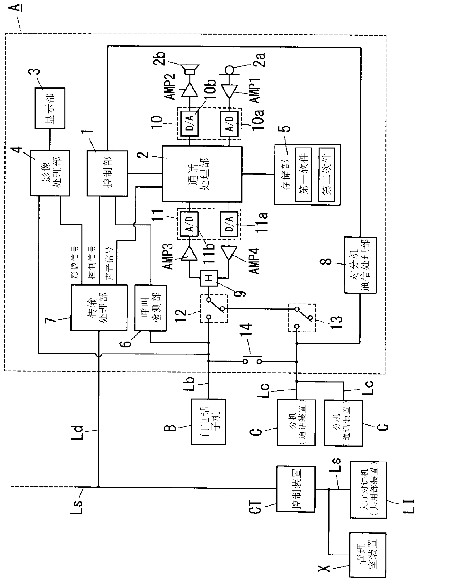
[0081] Below, refer to Figure 1~Figure 36 Embodiment 1 of the present invention will be described in detail. First, an intercom system for a condominium including the residential terminal according to the present invention will be described.
[0082] Such as figure 1 As shown, the intercom system for collective housing in this embodiment has: a common unit device (lobby intercom) LI, which is installed in the shared lobby (hall) of the collective housing; It is installed in each household of the collective housing; the door phone sub-machine B is installed in the outer hall of each household; the signal trunk line Ls is connected to the intercom LI in the lobby; the household line Ld is branched from the signal trunk line Ls and connected to the Residential machine A connection; In addition, there are: a control device CT, which is connected to the resident machine A and the hall intercom LI through the signal trunk line Ls and the residential line Ld; Send and receive vo...
Embodiment approach 2
[0304] Below, refer to Figure 37 , Figure 38 Embodiment 2 of the present invention will be described in detail. In addition, for the sake of clarity, the same elements as those of the intercom system for a condominium complex according to Embodiment 1 are assigned the same symbols and descriptions thereof are omitted.
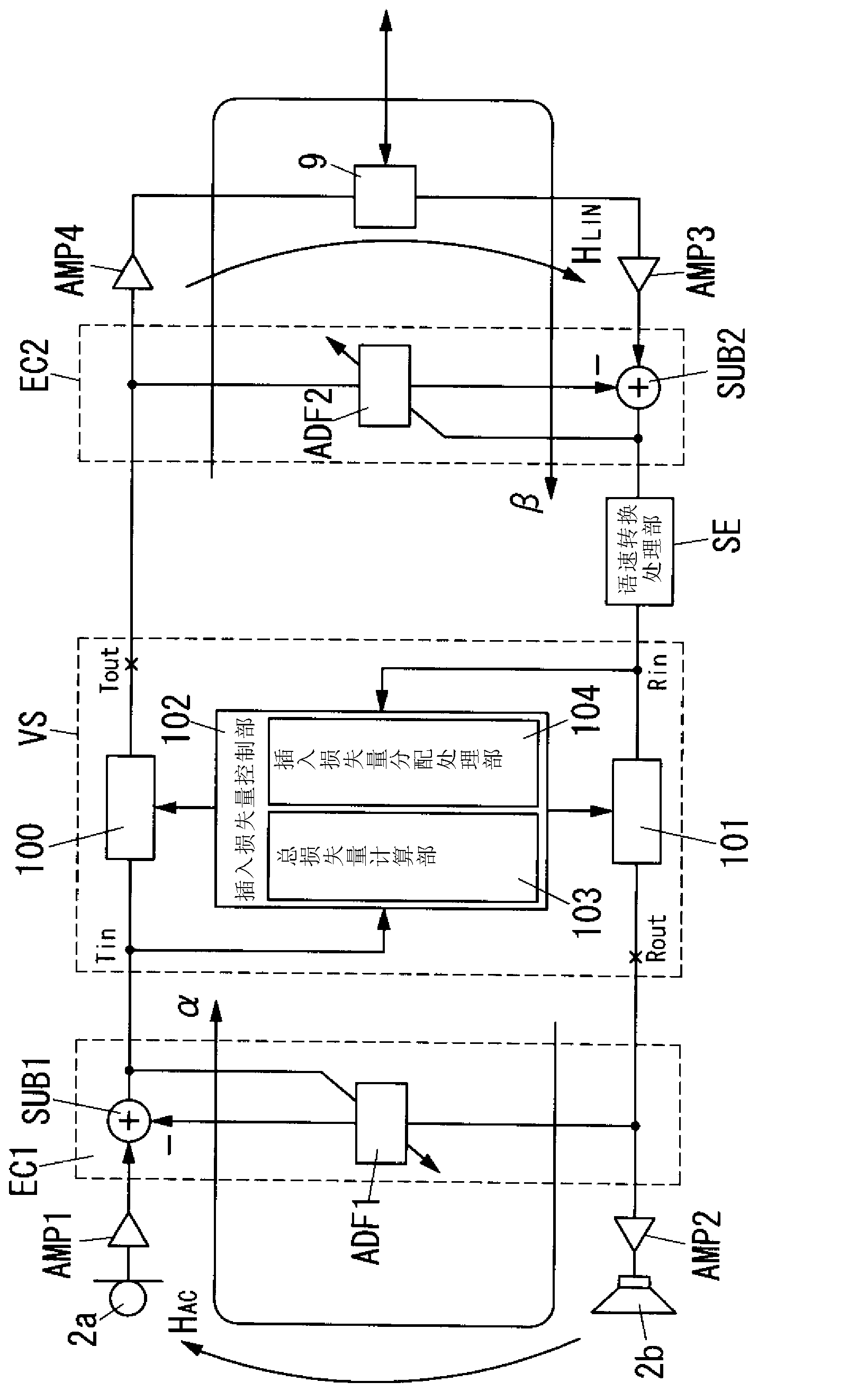
[0305] Both the voice data loss compensation process and the speech rate conversion process in Embodiment 1 described above use the pitch cycle of the voice, and therefore need to perform pitch cycle detection processing for detecting the pitch cycle of the voice. However, when the program for voice data loss compensation processing and the program for speech rate conversion processing are each provided with a program (program module) for pitch cycle detection processing, the memory for loading the programs is consumed unnecessarily. Therefore, in this embodiment, it is characterized in that the program of the pitch period detection process for detecting th...
Embodiment approach 3
[0316] Below, refer to Figure 39 A~ Figure 42 Embodiment 3 of the present invention will be described in detail. In addition, for the sake of clarity, the same elements as those in the intercom system for condominium complexes according to Embodiment 2 are assigned the same symbols and descriptions thereof are omitted.
[0317] The sound data missing detection unit 15 in this embodiment is synchronized with the first time interval T1 (=τ / m) obtained by dividing the time length τ of the sound data corresponding to one packet by the positive integer m and the input timing of the sound data. Detect absence of sound data. In addition, the pitch period detection unit 16 in this embodiment detects the pitch period in synchronization with the detection period Tx (=n×τ / m) that is a positive integer n times the first time interval T1 and the first time interval T1 .
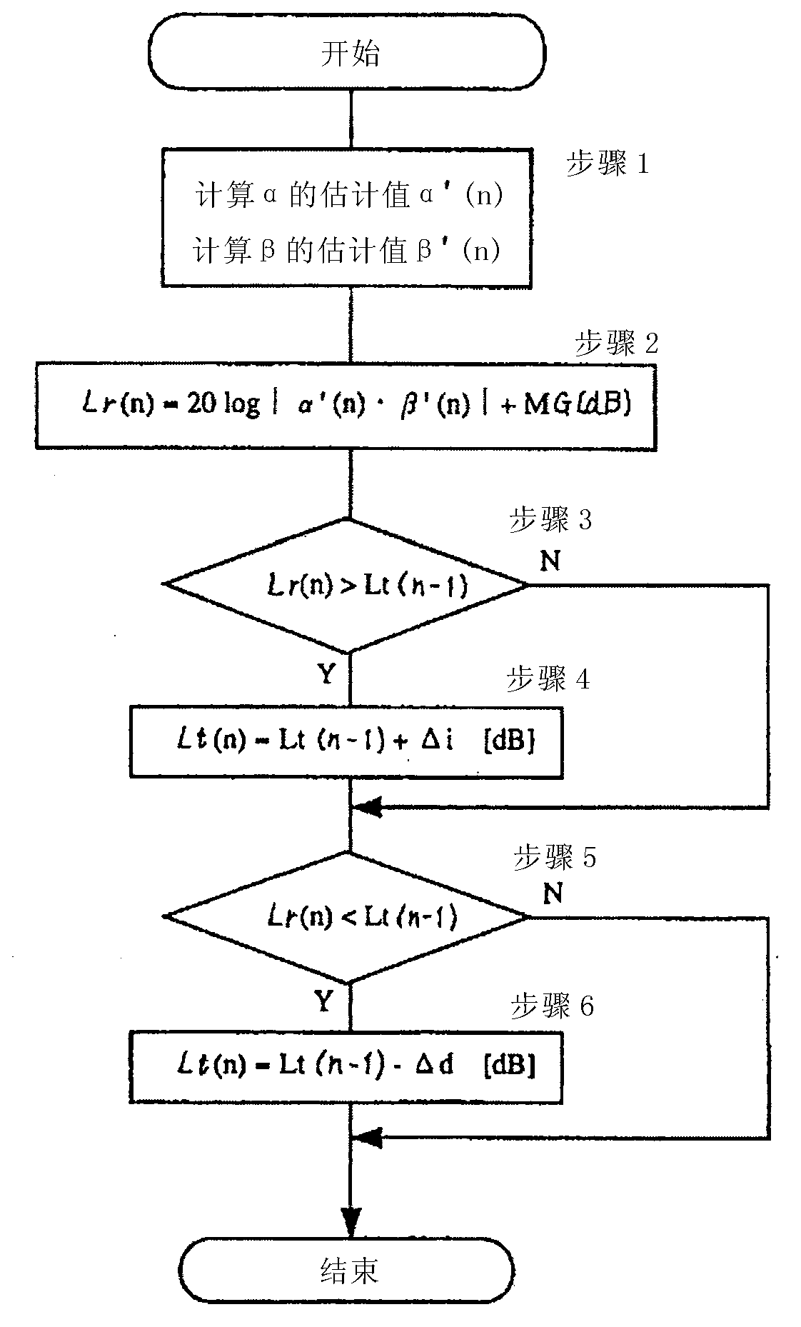
[0318] Here, refer to Figure 39 A and Figure 39 The execution timing of the voice data absence detection proce...
PUM
 Abstract
Description
Claims
Application Information
 - R&D
- Intellectual Property
- Life Sciences
- Materials
- Tech Scout
- Unparalleled Data Quality
- Higher Quality Content
- 60% Fewer Hallucinations
Browse by: Latest US Patents, China's latest patents, Technical Efficacy Thesaurus, Application Domain, Technology Topic, Popular Technical Reports.
© 2025 PatSnap. All rights reserved.Legal|Privacy policy|Modern Slavery Act Transparency Statement|Sitemap|About US| Contact US: help@patsnap.com