
Siting method of distribution centers

A distribution center and candidate address technology, applied in the field of logistics, can solve the problems of inapplicable distribution centers and inapplicable algorithms, and achieve the effects of compact distribution addresses, improved distribution efficiency, and simple and easy methods.

Inactive Publication Date: 2013-01-30
北京拉手网络技术有限公司
View PDF1 Cites 21 Cited by
  • Summary
  • Abstract
  • Description
  • Claims
  • Application Information

AI Technical Summary

Problems solved by technology

[0004] For only a large number of historical delivery addresses, most of the algorithms in the prior art, such as Baumer-Walff model, CFLP method, etc., are not applicable
These methods are often aimed at more complex logistics center planning and require the collection of a large amount of additional information
[0005] It can be seen that the above-mentioned existing distribution center site selection method is not applicable to the situation where the distribution center site is selected only based on the historical delivery address as data information

Method used


Image

  • Siting method of distribution centers
  • Siting method of distribution centers
  • Siting method of distribution centers

Examples


Embodiment 1

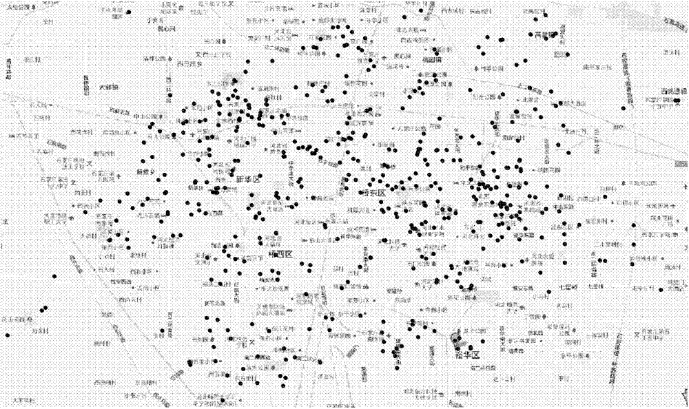
[0045] This embodiment is applicable to the scheme of one-time site selection. The location selection method of the distribution center includes the following steps:

[0046] 1) First select m addresses arbitrarily from the map of the target city as the candidate addresses of the distribution center;

[0047] 2) For the historical delivery addresses, assign them to the candidate addresses of the nearest delivery center according to their distances from the candidate addresses of these delivery centers. Among them, the Manhattan distance is used as the distance metric. For two points on the map, A(a1, a2), B(b1, b2), the Manhattan distance between A and B is defined as D(A, B)=|a1-b1|+|a2-b2| .

[0048] 3) Calculate the average point of the delivery address of the candidate address assigned to each distribution center, and use the average point as the candidate address of the new distribution center; because the selected distance is the Manhattan distance (that is, the absol...

Embodiment 2

[0053] This embodiment is applicable to the situation where the location of the distribution center is selected in stages. Take setting up distribution centers in two stages as an example, where the number of distribution centers set up in the first stage is m 1 The number of distribution centers set up in the second stage is m 2 indivual.

[0054] The method for location selection of distribution centers in stages includes the following steps:

[0055] 1) First select m arbitrarily from the target city map 1 +m 2 addresses as the candidate addresses of the distribution center, where m 1 The number of distribution centers set up for the first stage, m 2 The number of distribution centers set up for the second phase;

[0056] 2) For historical delivery addresses, assign them to the nearest candidate addresses according to their distance from the candidate addresses of these delivery centers;

[0057] 3) Calculate the average point of the historical delivery address of th...


PUM


Abstract

The invention discloses a siting method of distribution centers. The method includes the steps of firstly, optionally selecting m sites as candidate sites of the distribution centers on a map of a target city; secondly, assigning historical distribution sites to the candidate sites of the distribution centers the nearest to the historical distribution sites according to the distances from the historical distribution sites to the candidate sites of the distribution centers; thirdly, calculating an average site of the distribution site assigned to the candidate site of each distribution center as a new candidate site of the distribution center; fourthly, repeating the first and second steps till a standard measure function starts converging and the m average sites being the sites of the distribution centers. By siting by the siting method, the distribution sites of the distribution centers are as compact as possible, and the distribution centers are as separate as possible. Finally, distribution cost is locally optimized.

Description

technical field [0001] The invention relates to the technical field of logistics, in particular to a method for selecting the location of a distribution center in the logistics field. Background technique [0002] The correct location of the distribution center can enable the distribution center to effectively cover the distribution range, minimize the distribution cost and maximize the profit. The research on location selection of logistics distribution centers in foreign countries has a history of more than 60 years. The location selection of various types of logistics distribution centers has made remarkable achievements in theory and practice, and many practical methods have been formed. Domestic research on location selection of logistics distribution centers started relatively late, but after more than ten years of research, great achievements have been made in theory and practice. [0003] The method of site selection is divided into quantitative method of single sit...

Claims


Application Information

Patent Timeline
IPC IPC(8): G06Q10/08G06Q50/28
Inventor 沈志勇靳简明熊宇红
Owner 北京拉手网络技术有限公司
Learn More