
Measuring element, force sensor and measuring assembly for measuring forces

A technology of force measuring sensor and measuring element, applied in the direction of measuring force, force/torque/work measuring instrument, measuring device, etc. Effects of material properties

Active Publication Date: 2013-01-23
MAGNA STEYR FAHRZEUGTECHN
View PDF8 Cites 7 Cited by
  • Summary
  • Abstract
  • Description
  • Claims
  • Application Information

AI Technical Summary

Problems solved by technology

[0005] The disadvantage of the measuring element disclosed in CN 2156494 Y is that it is relatively complex in terms of design and relatively large in terms of volume

Method used


Image

  • Measuring element, force sensor and measuring assembly for measuring forces
  • Measuring element, force sensor and measuring assembly for measuring forces
  • Measuring element, force sensor and measuring assembly for measuring forces

Examples


Embodiment Construction

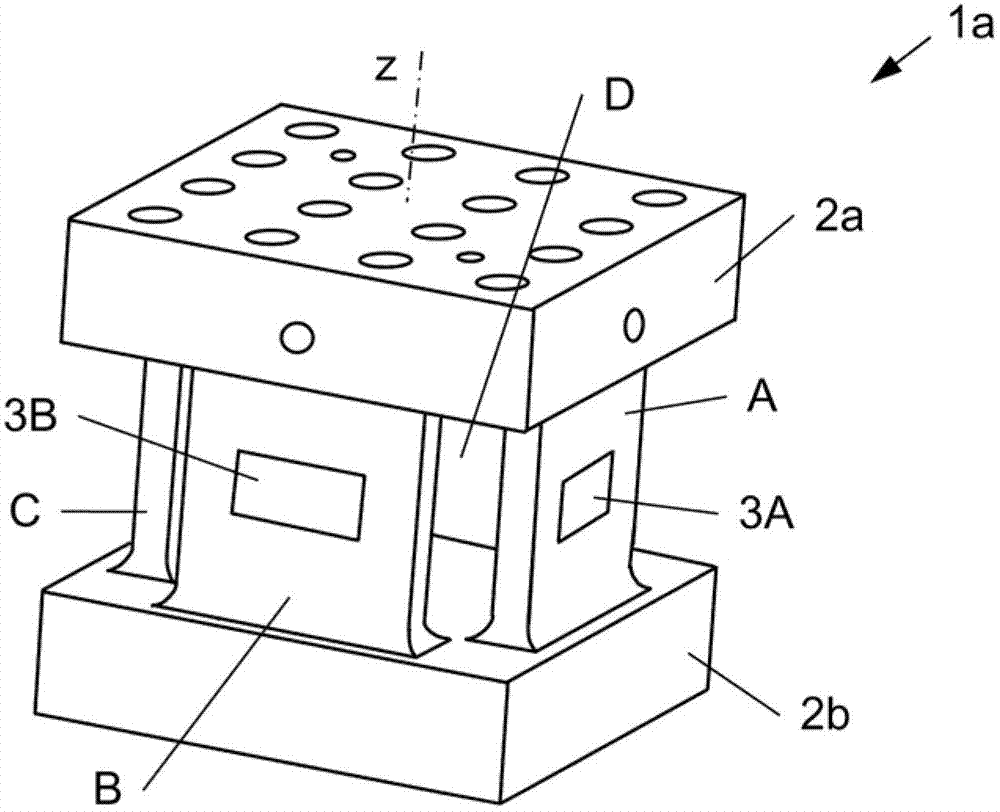
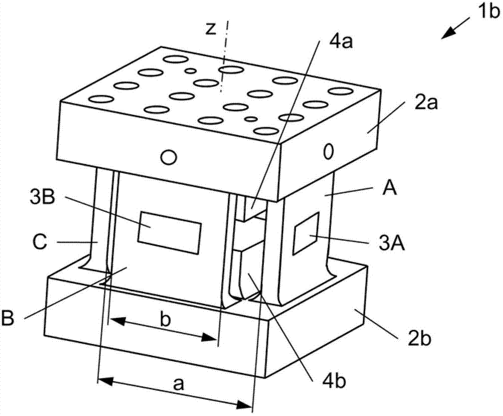
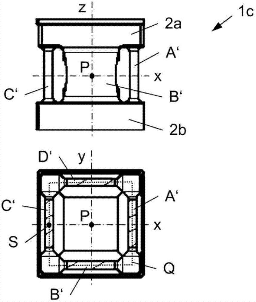
[0061] figure 1 A first example of a measuring element 1a for force measurement is shown, comprising two mutually spaced apart cores 2a, 2b each having at least one mounting surface for introducing the force to be measured, and four identical The webs A..D spaced apart from each other, oriented along the longitudinal axis z, are arranged in a square and connect the two cores 2a, 2b at connecting surfaces spaced apart along the longitudinal axis. Load cells 3A..3D are arranged on each of said webs A..D. Otherwise, the measuring cell 1a does not comprise a further load cell.

[0062] exist figure 1 In the example specifically shown in , the core parts 2a, 2b are identical and have mounting surfaces parallel to each other, and a plurality of mounting holes are provided in the mounting surfaces. In this example, the webs A..D of the measuring cell 1 a are formed as prisms, which are oriented parallel to the longitudinal axis z and have a rectangular cross-section. Furthermore,...


PUM


Abstract

The invention relates to a measuring element, a force sensor and a measuring assembly for measuring forces. The measuring element (1a..1c) for measuring forces comprises two spaced-apart core portions (2a, 2b) and four identical spaced-apart webs (A..D, A'..D') which are aligned along a longitudinal axis (z) and are arranged in a square (Q), connecting the two core portions (2a, 2b). Force sensors (3a, 3b, 3A..3D, 11, 12, 21, 22, 31..34) are only provided to the webs (A..D, A6..D6). Further, the force sensors (3a, 3b, 3A..3D) include two first strain gauges (11, 12) for measuring a force in a first direction (z), two second strain gauges (21, 22) for measuring a force perpendicular to the first direction (z), at least one third strain gauge (31, 33) for measuring a force at an angle of +45 degrees to the first direction (z) and at least one fourth strain gage (32, 34) for measuring a force at an angle of -45 degrees to the first direction (z). The strain gages (11, 12, 21, 22, 31..34) are arranged on a common substrate. Finally, a measuring assembly to be used with the measuring element (1a..1c) is provided.

Description

[0001] related application [0002] The present invention is based on provisional application US61 / 509,185 filed in the United States on July 19, 2011 and EP 12158446.0 filed in the European Patent Office on March 7, 2012, both of which are hereby incorporated by reference. technical field [0003] The invention relates to a measuring element for force measurement, comprising two cores spaced apart from each other, each having at least one mounting surface for introducing a force to be measured; four identical webs spaced apart from each other (web), webs oriented along the longitudinal axis, arranged in a square, and connected to the two cores at webs spaced apart along the longitudinal line; and load cells on each of the webs. The invention also relates to a load cell and a measuring assembly for force measurement, in particular in combination with the measuring element described at the outset. Background technique [0004] Deformation force measurement by means of measur...

Claims


Application Information

Patent Timeline
Patent Type & Authority Applications(China)
IPC IPC(8): G01L1/22
CPCG01L5/161G01L1/2243G01L5/1627
Inventor A.梅尔莫尔M.米特什F.罗比尔
Owner MAGNA STEYR FAHRZEUGTECHN
Learn More