Device support arm

A technology for supporting arms and hinge devices, which is applied to supporting machines, machines/brackets, mechanical equipment, etc., can solve the problems of easy falling of the device, reduced ability to support monitors, and the influence of vibration, etc., to achieve the effect of easy change and adjustment

Active Publication Date: 2014-10-01
TAKIGEN MFG CO LTD
View PDF1 Cites 0 Cited by
  • Summary
  • Abstract
  • Description
  • Claims
  • Application Information

AI Technical Summary

Problems solved by technology

[0003] However, in the above-mentioned conventional device support arms, each joint member between a plurality of arms is constituted by a hinge mechanism that provides frictional resistance between the arms only by using butterfly springs or washers, since only the butterfly The frictional resistance action of springs or washers, etc. bears the load of various devices such as monitors and the load of various arms, so the load is too large for the ability of this joint part to maintain the angle between the arms
Therefore, the problem with this support arm is that the ability to support various devices such as monitors gradually decreases shortly after use, and the device gradually falls, so that it cannot be stably maintained at the specified position required by the user for a long time.
In addition, when such a device supporting arm is used in a vehicle, for example, it is easily affected by vibrations, so the supported device tends to fall, making it difficult to maintain the most suitable position for the user stably for a long time.

Method used


Image

  • Device support arm
  • Device support arm
  • Device support arm

Examples


Embodiment Construction

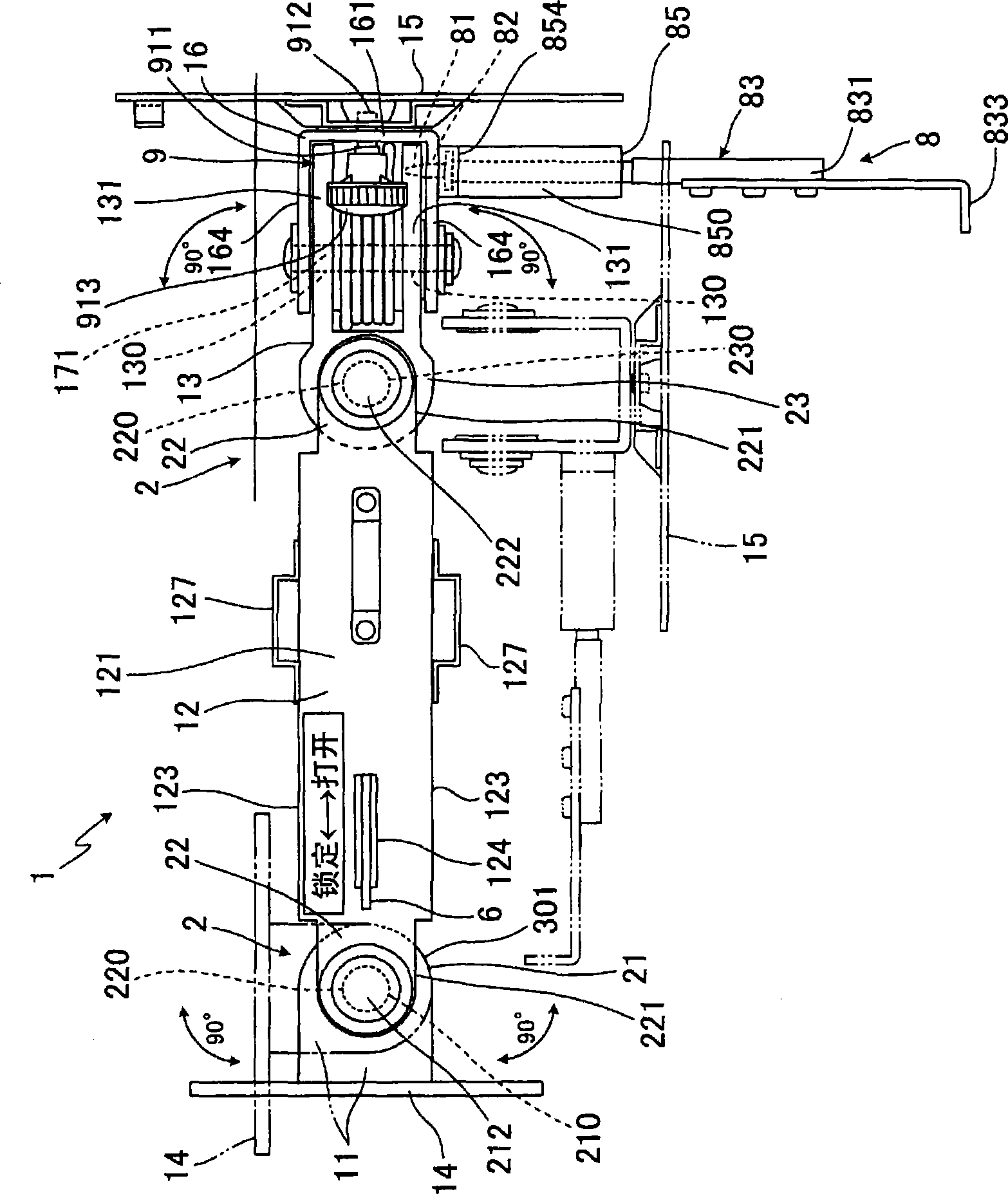
[0127] Hereinafter, modes for implementing the present invention will be described with reference to the drawings. In this embodiment, the device support arm of the present invention is specifically exemplified as a monitor arm for installing a monitor in a vehicle such as a car or a truck, and in the following description, this machine support arm is referred to as a monitor arm.

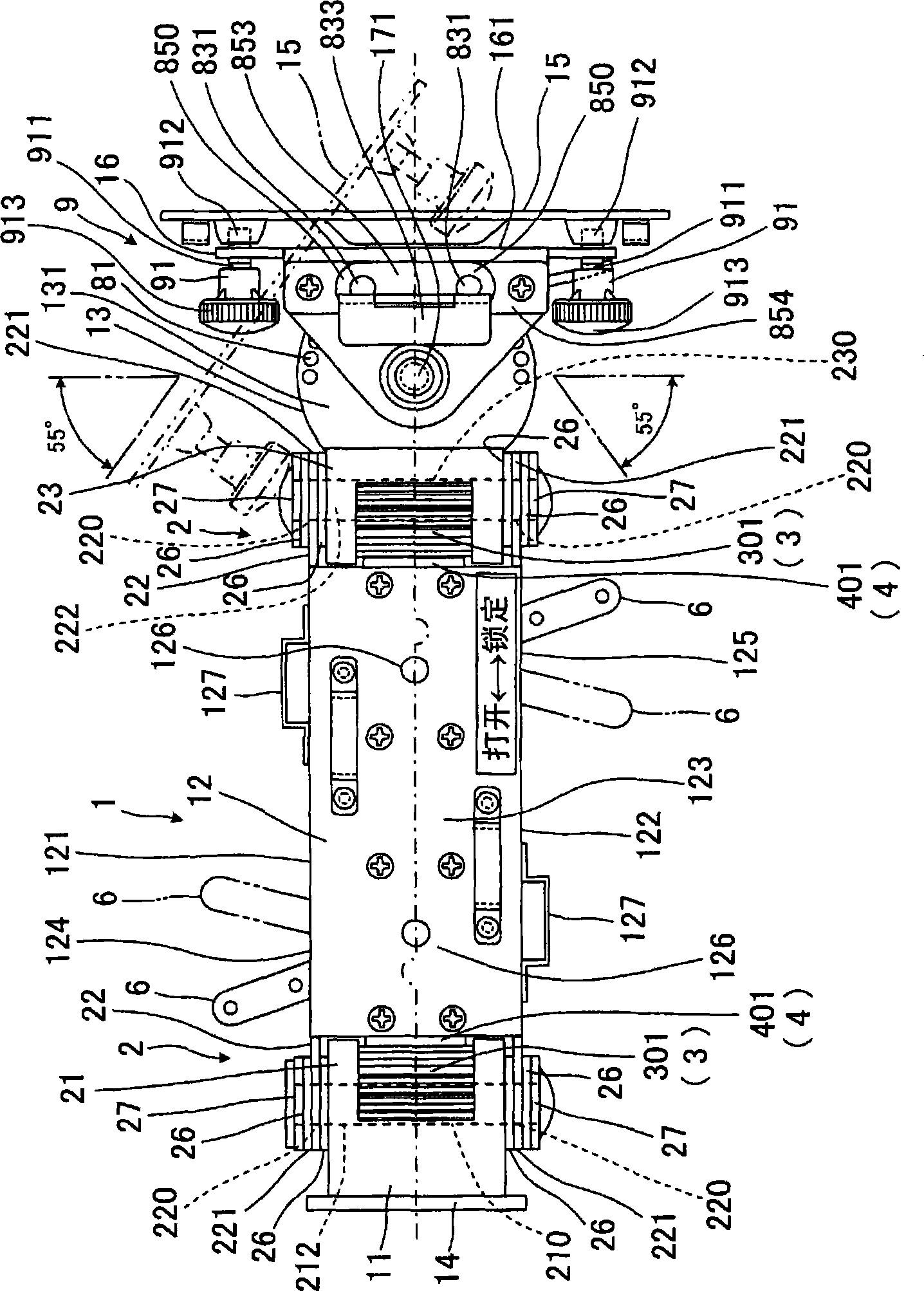
[0128] like figure 1 as well as figure 2 As shown, the monitor arm 1 is provided with a plurality of arms 11 , 12 , 13 . The arms 11, 12, 13 are rotatably connected to each other through the hinge device 2, 2 in the horizontal direction (left-right direction) or vertical direction (up-down direction), and the arms 11, 12, 13 can maintain any rotation angle. connect. In addition, on the base end side arm 11, a fixed base 14 is provided for supporting and fixing all the arms 11, 12, 13 on the instrument panel or the like in the vehicle cab as the installation end, and on the front end side arm 13...


PUM


Abstract

The device supporting arm is composed of a plurality of arms, one adjacent arm is provided with a fixed-side positioning guide provided on its bearing, and the other arm is provided with a movable-side positioning guide, a lever with a push member, and a locking portion . After adjusting the adjacent arms at any rotational angle, by rotating the operating lever in a predetermined direction, the movable side positioning guide is pushed toward the fixed side positioning guide by the pushing member, so that the pushing The part engages with the locking portion to lock the rotational angle between the arms. Unlock by turning the lever in the opposite direction. With this structure, it is possible to stably hold various devices such as monitors at predetermined positions required by the user for a long period of time.

Description

technical field [0001] The present invention relates to a device supporting arm for supporting monitors, computers, televisions and other various devices so as to be freely movable in left and right directions or in up and down directions. Background technique [0002] Conventionally, various devices such as monitors, computers, and televisions have been installed in offices, homes, etc., or in vehicles such as automobiles, airplanes, ships, etc., with various types of device support arms. In general, a plurality of arms of the device supporting arm are rotatably connected to each other by a hinge device, and each arm is connected so as to maintain any rotation angle, and the base end side arm is fixed at the installation end, and the front end side arm is installed. Various means are provided on the mounting end so that the various means are freely movable within the length of each arm. For example, Japanese Patent JP-9-326980-A discloses such a device support arm. In the...

Claims


Application Information

Patent Timeline
Patent Type & Authority Patents(China)
IPC IPC(8): F16M11/06F16M11/16F16M11/18
CPCF16M11/10F16M11/18F16M13/02
Inventor 濑川志朗
Owner TAKIGEN MFG CO LTD
Why Eureka
Try Eureka