Asynchronous door knife of elevator door machine
An elevator door operator and door knife technology, applied in the field of elevator accessories, can solve the problems of poor stability of the connecting rod, poor clamping of the landing door to link the door ball, increased cost, etc., and achieves convenient assembly and adjustment, less consumables, and low cost. Effect
- Summary
- Abstract
- Description
- Claims
- Application Information
AI Technical Summary
Problems solved by technology
Method used
Image
Examples
Embodiment 1
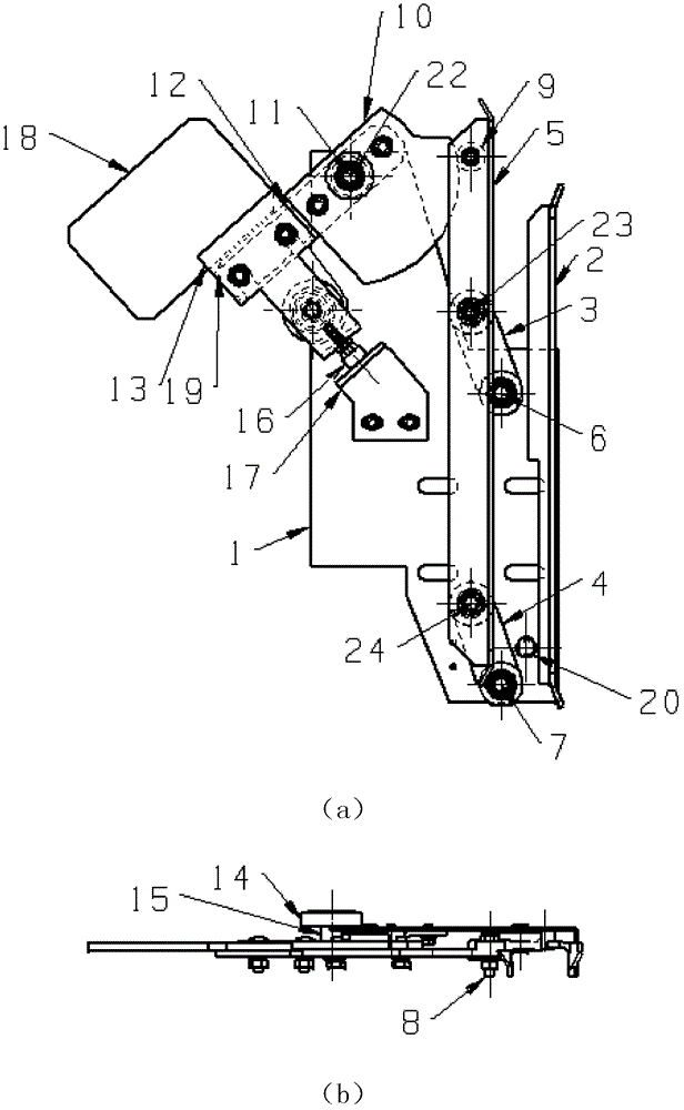
[0040] see figure 1 As shown, the door knife assembly includes: a fixed blade 2, an upper swing rod 3, a lower swing rod 4, a movable blade 5, a roller 9, a first cam 10, a roller 14, a limit screw 16, a baffle 17, Weight 18. in, figure 1 (a) is the front view, figure 1 (b) is figure 1 (a) Top view.
[0041] The fixed blade 2 and the movable blade 5 are arranged in parallel. The fixed blade 2 is installed on the mounting plate 1, and the shaft 6 for the upper swing link, the shaft 7 for the lower swing link and the shaft 11 for the first cam are also installed on the mounting plate 1.
[0042] The upper shaft 23 and the lower shaft 24 are installed on the movable blade 5; the two ends of the upper swing rod 3 are provided with bearings, one end is installed on the upper swing rod shaft 6 of the mounting plate 1, and the other end is installed on the shaft 6 of the movable blade 5. On the upper shaft 23; the two ends of the lower fork 4 are provided with bearings, one end...
Embodiment 2
[0064] As shown in FIG. 9 , the installation and mutual connection relationship of 1 to 26 is the same as that of Embodiment 1, and 32 to 39 are added in this embodiment. First, a shaft capable of installing bearings at both ends is used instead of the shaft 11 for the first cam in the original embodiment 1 to become a common shaft for the first cam and the lever. Manufacture lever 32, there is a round hole in the middle of the lever 32 and a bearing is installed, the center of the round hole is concentric with the center of rotation 22, the lever 32 is installed on the first cam and the lever common shaft 39, the position of the lever 32 is on the mounting plate 1, now the center of rotation of the lever and the center of revolution 22 are concentric. One end of the lever is bent to a certain width, and is pressed against the roller 14 below, and the other end of the lever is provided with a shaft 34 for the roller B, and the roller B is installed on the axle. The second cam...
PUM
 Abstract
Description
Claims
Application Information
 - R&D
- Intellectual Property
- Life Sciences
- Materials
- Tech Scout
- Unparalleled Data Quality
- Higher Quality Content
- 60% Fewer Hallucinations
Browse by: Latest US Patents, China's latest patents, Technical Efficacy Thesaurus, Application Domain, Technology Topic, Popular Technical Reports.
© 2025 PatSnap. All rights reserved.Legal|Privacy policy|Modern Slavery Act Transparency Statement|Sitemap|About US| Contact US: help@patsnap.com


