
Electronic adjsuting method, device and system

A technology of electric adjustment and electric adjustment antenna equipment, which is applied in the field of communication, and can solve the problems of inability to perform ALD equipment operation, poor operability of electric adjustment operation of ALD equipment, and inconvenient operation

Active Publication Date: 2012-12-19
HUAWEI TECH CO LTD
View PDF4 Cites 6 Cited by
  • Summary
  • Abstract
  • Description
  • Claims
  • Application Information

AI Technical Summary

Problems solved by technology

[0003] Under the existing technology, the threshold value of the power supply current of the ESC master device to the ESC antenna device (Antenna Line Device, ALD) is fixed, and the maximum operating current of the ALD device is also fixed. Different manufacturers and different The maximum operating current of the ALD equipment of the model can be different, but the main equipment of the ESC does not know the maximum operating current of the ALD equipment
The disadvantage of the existing technology is that when the ESC master device is connected to a new type of ALD device or cascade connected to a new ALD device, maintenance personnel need to reconfigure the power supply current threshold according to the maximum operating current of the ALD device; if the maintenance personnel do not reconfigure The power supply current threshold value, or the reconfigured power supply current threshold value cannot meet the maximum operating current of the ALD device. The operation of the ESC may cause the current of the main ESC device to exceed the protection threshold, thereby closing the port, and the operation of the ALD device cannot be performed. At this time, the operation of the ALD device can only be continued by manually modifying the power supply threshold of the ESC main device.
Therefore, under the prior art, the operability of the electric adjustment operation of the ALD equipment is poor, and the operation is inconvenient

Method used

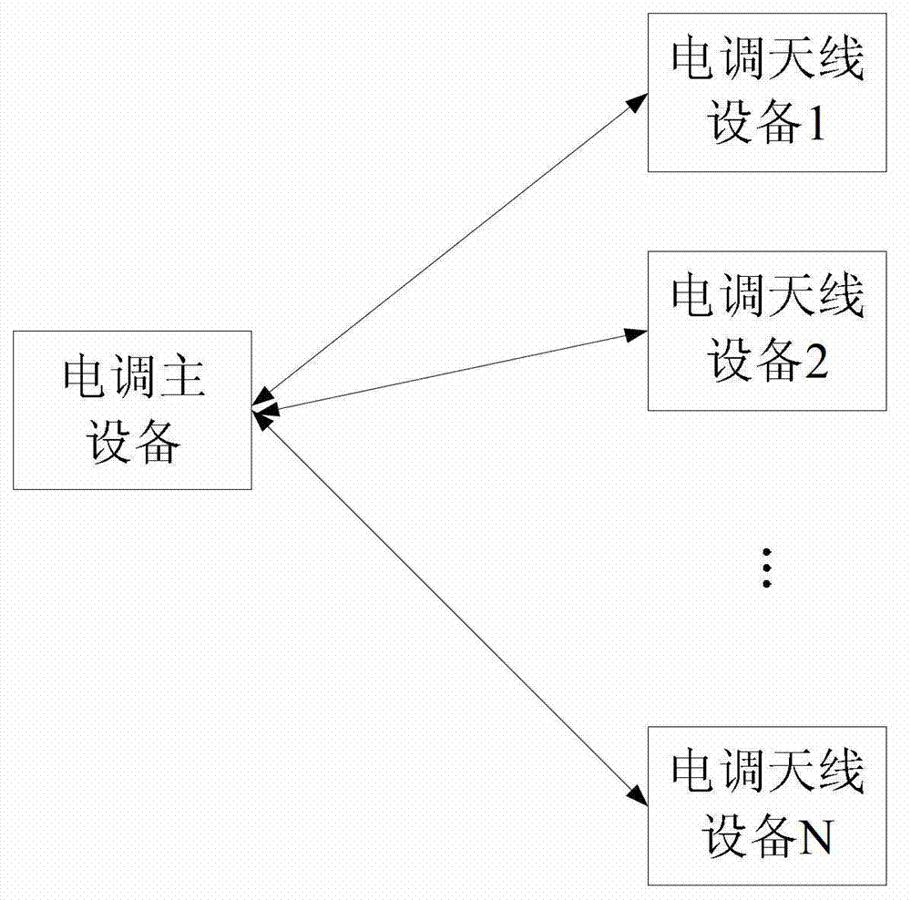
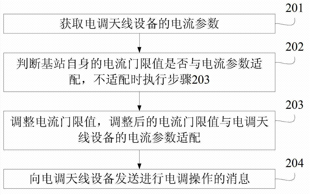
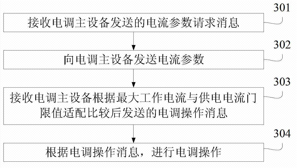

Image

  • Electronic adjsuting method, device and system
  • Electronic adjsuting method, device and system
  • Electronic adjsuting method, device and system

Examples


Embodiment Construction

[0061] In the following description, for purposes of illustration rather than limitation, specific details such as specific system architectures, interfaces, and techniques are set forth in order to provide a thorough understanding of the present invention. It will be apparent, however, to one skilled in the art that the invention may be practiced in other embodiments without these specific details. In other instances, detailed descriptions of well-known devices, circuits, and methods are omitted so as not to obscure the description of the present invention with unnecessary detail.

[0062] figure 1 It is a schematic diagram of an application scenario of an electric regulation method provided by an embodiment of the present invention. The electric regulation method, device and system provided by the embodiments of the present invention can be used as a new electric regulation method in all scenarios where the electric regulation is performed. Assuming that the threshold valu...


PUM


Abstract

The present invention relates to an electronic adjusting method, a device and a system. The method comprises the display unit comprises a display screen and a processor, and is operable by a mode switch; the mode switch is operated by relative pivotal motion between the display unit and the base receptacle; characterized in that the display unit and the base receptacle are complementarily shaped to cooperatively form a hinge axis about which the mode changing pivotal motion takes place. A performance display device having a hinge axis formed by the complementarily shaped display unit and base receptacle provides a simple, robust, and reliable device.

Description

technical field [0001] The present invention relates to the communication field, in particular to an electric regulation method, device and system. Background technique [0002] In mobile communication systems, electrically adjustable antennas have become mainstream, and the electrically adjustable antenna optimizes the network by adjusting the electrical downtilt angle of the antenna. [0003] Under the existing technology, the threshold value of the power supply current of the ESC master device to the ESC antenna device (Antenna Line Device, ALD) is fixed, and the maximum operating current of the ALD device is also fixed. Different manufacturers and different The maximum operating current of the ALD equipment of different models can be different, but the ESC main equipment does not know the maximum operating current of the ALD equipment. The disadvantage of the existing technology is that when the ESC master device is connected to a new type of ALD device or cascade conne...

Claims


Application Information

Patent Timeline
IPC IPC(8): H04W24/02
CPCH01Q3/00H01Q3/267H04W24/02H04W16/28
Inventor 吴立昌李悦
Owner HUAWEI TECH CO LTD
Learn More