
Non-contact dip angle measuring device and method

A non-contact, measuring device technology, applied in the field of measurement, can solve problems such as inconvenient operation, high requirements for measurement angle of view, and the need for contact between the measuring instrument and the measured object, so as to improve measurement efficiency and accuracy and reduce labor intensity , the effect of accurate inclination measurement

Active Publication Date: 2012-11-28
SHOUGANG JINGTANG IRON & STEEL CO LTD
View PDF4 Cites 13 Cited by
  • Summary
  • Abstract
  • Description
  • Claims
  • Application Information

AI Technical Summary

Problems solved by technology

[0002] The existing inclination measuring devices are mainly contact-type, by measuring the contact between the reference surface and the measured object, using a gravity vertical device (such as a weight) and an angle dial to read or use an inclination sensor to measure the inclination angle, this measurement method The measuring instrument and the object to be measured must be in contact. When measuring distant objects and objects that are not suitable for humans to approach (such as objects in dangerous environments such as high temperature and dust), it is necessary to make a large-scale angle conversion device (such as a T-square) for indirect measurement. The operation is very inconvenient, and at the same time, it is difficult to ensure the measurement accuracy by the dial reading method
At present, there are also non-contact methods for measuring inclination angles, such as vision or image processing, but the inclination angle of the measured target must be completely within the visual angle of view of the measurer to measure, which has higher requirements for the measurement angle of view

Method used


Image

  • Non-contact dip angle measuring device and method
  • Non-contact dip angle measuring device and method

Examples


Embodiment Construction

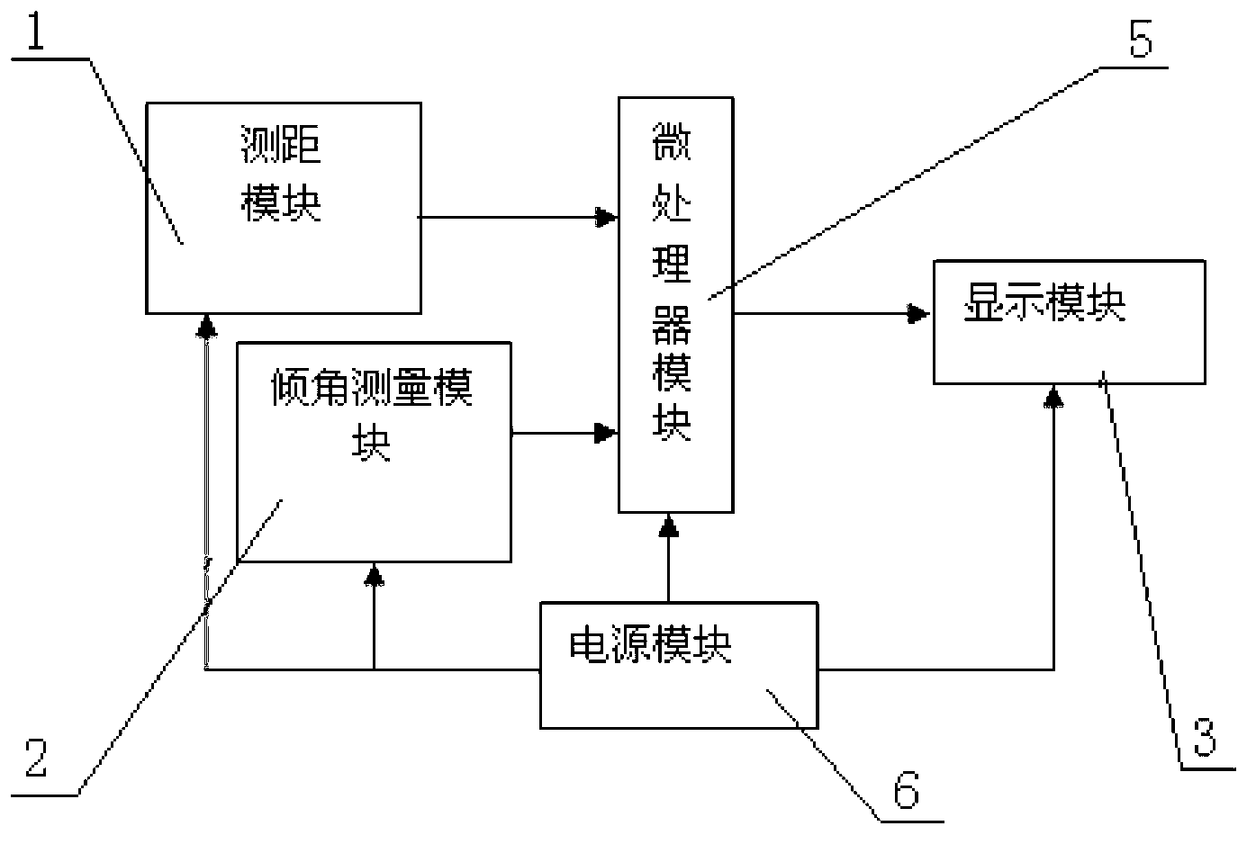
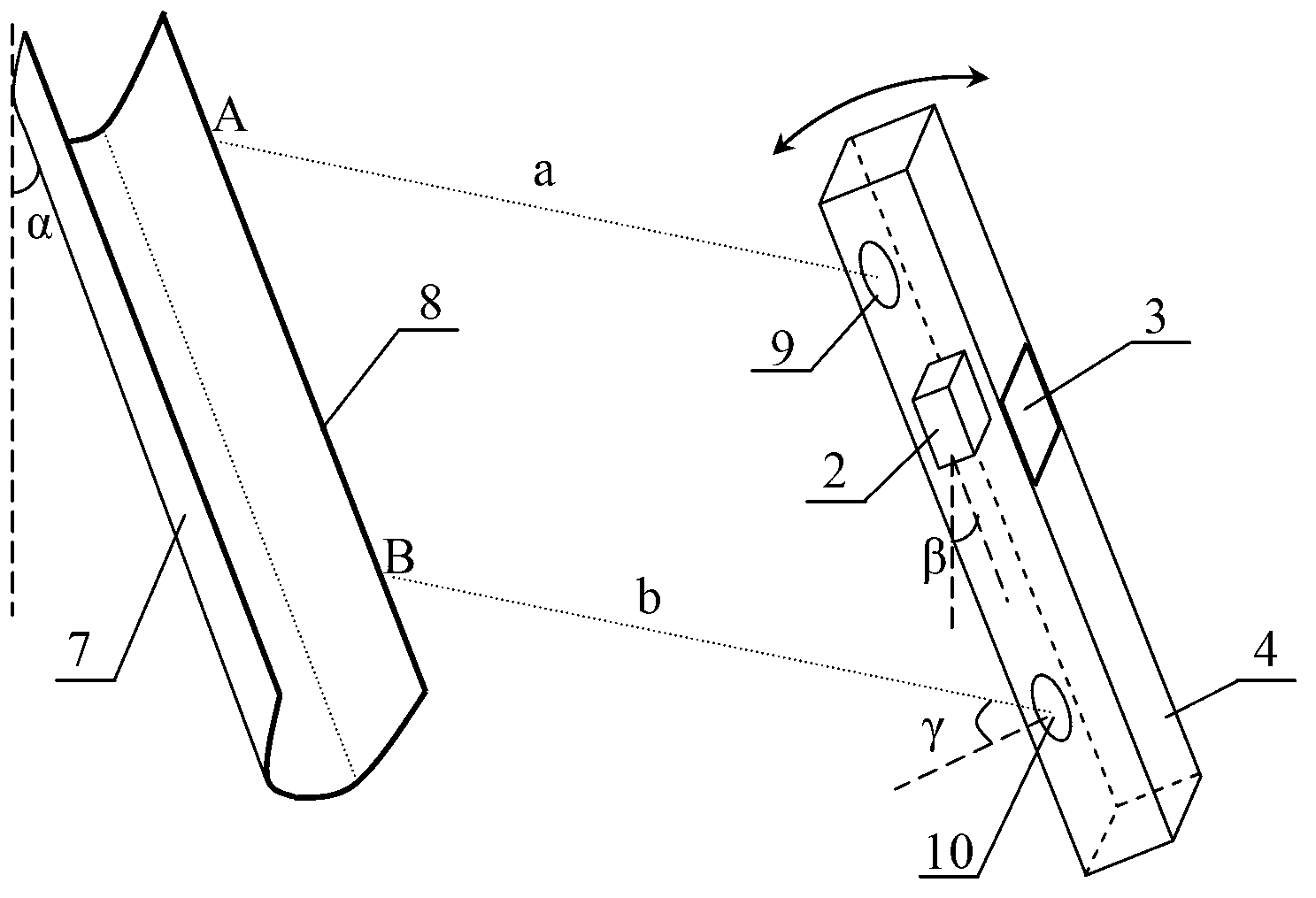
[0017] see figure 1 and figure 2 , a non-contact inclination measuring device provided by an embodiment of the present invention includes a body 4 on which a distance measuring module 1, an inclination measuring module 2, a microprocessor module 5, a display module 3, and a power supply module 6 are arranged. , the ranging module 1, the inclination measuring module 2 and the display module 3 are respectively connected with the microprocessor module 5, the power supply module 6 is connected with other modules, the ranging module 1 is installed on one side of the body 4, and the ranging module 1 is installed. One side serves as a measurement reference surface at the same time, and the other side of the main body 4 is installed with a display module 3 . The ranging module 1 is composed of two independent laser ranging units 9 and 10 with the same accuracy. The laser ranging unit 9 and the laser ranging unit 10 are separated by a certain distance on the body 4, and the distance ...


PUM


Abstract

The invention discloses a non-contact dip angle measuring device and a method thereof. The non-contact dip angle measuring device comprises a distance measuring module, a dip angle measuring module, a microprocessor module, a display module, a power supply module and a main body, wherein the distance measuring module comprises two independent laser distance measuring units which send two parallel measuring paths from the measuring reference surface of the main body when measuring, and the two paths are sent to characteristic lines of a target to be measured; the distance measured by the two laser distance measuring units and the dip angle of the main body measured by the dip angle measuring module are processed by the microprocessor module to be output to the display module; two distance values can be equalized by adjusting the inclining angle of the main body; in addition, the main body, the two measuring paths and the characteristic lines of the target to be measured form a parallelogram; and the dip angle displayed by the display module is equal to the dip angle of the target to be measured. The non-contact dip angle measuring device and the method thereof, both provided by the invention, can conveniently carry out non-contact high-precision dip angle measurement for the target to be measured, particularly the target which is in a long distance, cannot be easily reached by human beings or has an imperfect measuring visual angle.

Description

technical field [0001] The invention relates to the field of measurement technology, in particular to a non-contact inclination measuring device and method. Background technique [0002] The existing inclination measuring devices are mainly contact-type, by measuring the contact between the reference surface and the measured object, using a gravity vertical device (such as a weight) and an angle dial to read or use an inclination sensor to measure the inclination angle, this measurement method The measuring instrument and the object to be measured must be in contact. When measuring distant objects and objects that are not suitable for humans to approach (such as objects in dangerous environments such as high temperature and dust), it is necessary to make a large-scale angle conversion device (such as a T-square) for indirect measurement. The operation is very inconvenient, and the way of dial reading is also difficult to ensure the measurement accuracy. At present, there ar...

Claims


Application Information

Patent Timeline
IPC IPC(8): G01B11/26
Inventor 郭之明沈海波
Owner SHOUGANG JINGTANG IRON & STEEL CO LTD
Learn More