
Method and device for transparent imaging

An imaging device and imaging technology, applied in optical components, optics, instruments, etc., can solve problems such as unsolved problems, inability to comprehensively solve problems, passive problems, etc.

Active Publication Date: 2016-07-20
梁雁飞
View PDF5 Cites 0 Cited by
  • Summary
  • Abstract
  • Description
  • Claims
  • Application Information

AI Technical Summary

Problems solved by technology

[0009] The above various existing technical solutions try to prevent the imaging source from being discovered by the observer as much as possible, but they cannot solve the problem in an all-round way. They simply adopt some evasive occlusions, which not only cannot play the role The best display effect and function of this kind of equipment, and its imaging source may be found by the observer at any time, very passive, so the problem is still not solved in essence

Method used


Image

  • Method and device for transparent imaging
  • Method and device for transparent imaging
  • Method and device for transparent imaging

Examples


Embodiment Construction

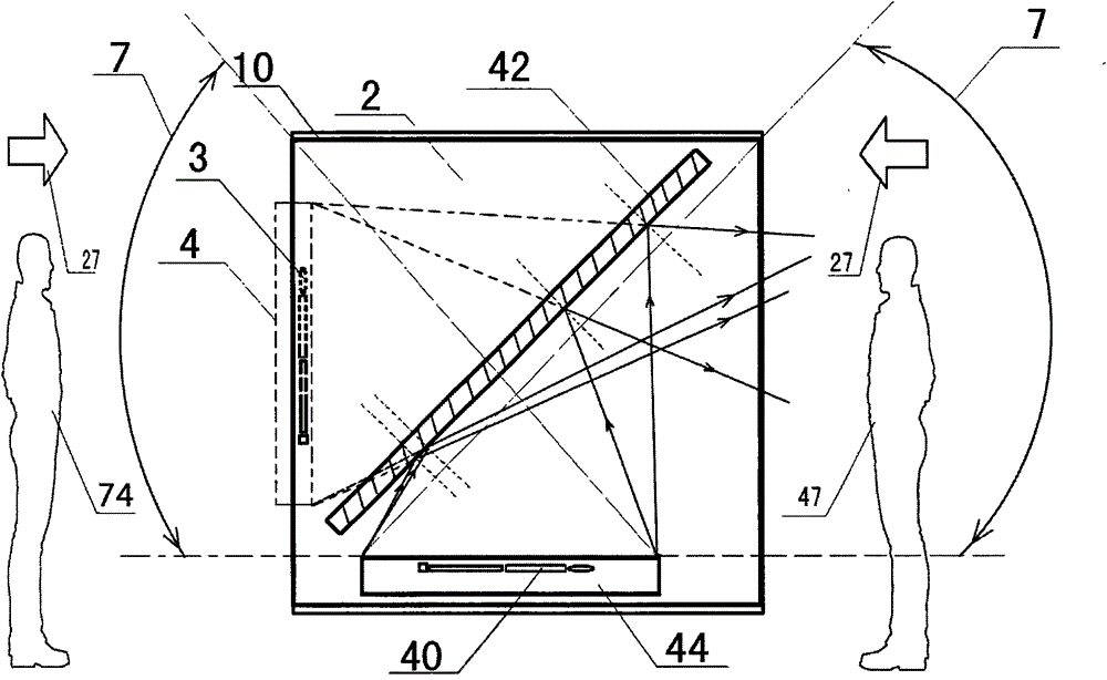
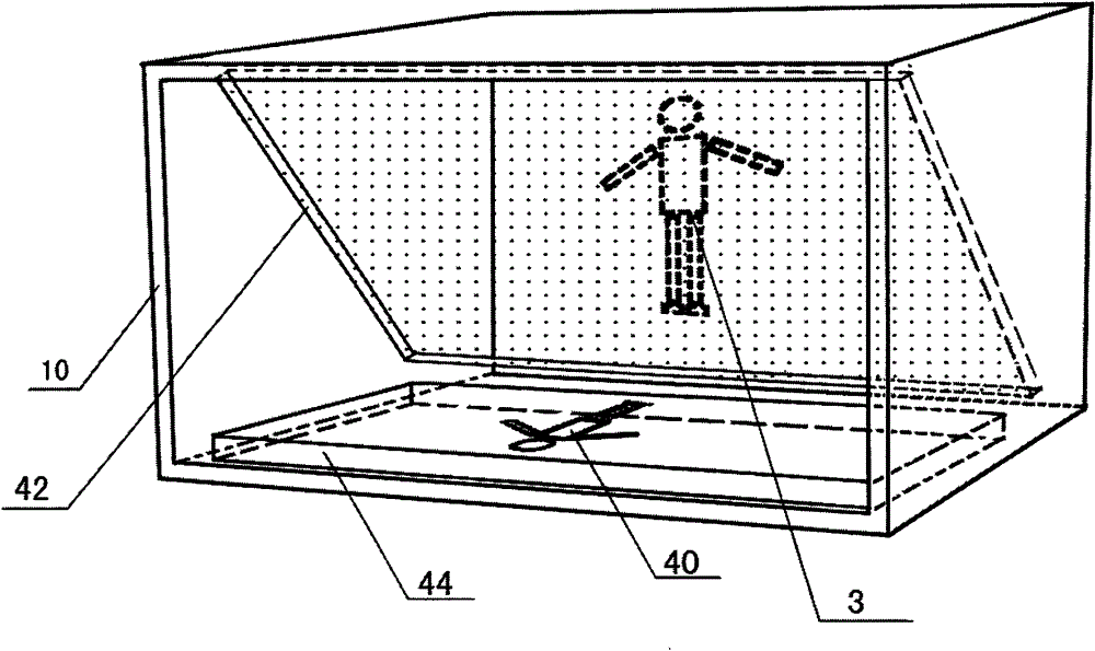
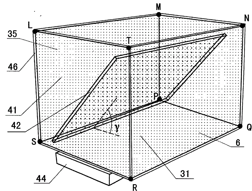
[0074] The present invention will be described in further detail below in conjunction with the accompanying drawings and embodiments.

[0075] Refer below Figure 10 and Figure 11 The first embodiment of the present invention is described in the case of single-sided imaging to display a single-layer image.

[0076] Such as Figure 10 As shown, the housing 45 is made of an opaque plate, an open frame formed by removing two opposite faces from a cuboid, and is used to support and fix the display screen 44 and the transparent container 46. The transparent container 46 is a cuboid with a top cover Container, its inner cavity is also a cuboid, that is, angle β=90 °; the coated reflective glass 42 is put into the container 46, so that the reflective surface of the coated reflective glass 42 is at an angle of 45 ° with the bottom surface of the container 46, and the reflective surface of the coated reflective glass 42 Towards the direction of the opening of the housing 45, fill t...


PUM


Abstract

The invention relates to a method and an apparatus, and the method and the apparatus can make an imaging source hidden when catoptric imaging occurs, and enable an observer to watch displayed transparent images from an optimum viewing angle and an optimum sight distance. The method comprises the imaging source and a reflecting medium. The method is characterized by comprising light emitted by the imaging source striking a first refracting surface of an optically denser medium from an optically thinner medium, occurring a refraction, and then the light striking the optically thinner medium from the optically denser medium, a total reflection or a refraction occurring on a second refracting surface of the optically denser medium. The light emitted by the imaging source strikes the first refracting surface of the optically denser medium from the optically thinner medium, the refraction occurs, and the refracted light strikes the reflecting medium from the optically denser medium, the reflection occurs, and then the reflected light strikes the second refracting surface of the optically thinner medium. The light emitted by a background object strikes a third refracting surface of the optically denser medium from the optically thinner medium, the refraction occurs, and the refracted light strikes the reflecting medium and the light passes through the reflecting medium and strikes the second refracting surface.

Description

technical field [0001] The present invention relates to a transparent imaging method and device, in particular to a reflective imaging method and device for making observers unable to see the imaging source of the transparent image at all positions where the transparent image can be seen. The invention is especially suitable for improving the sense of mystery, sense of science and technology and sense of three-dimensionality of transparent images. Background technique [0002] The continuous breakthrough of display technology has produced a variety of display products, from CRT display, LCD display, LED display, three-dimensional display, to OLED display with development potential in recent years, all of which reflect the progress of the times, among which OLED The display screen is more energy-efficient, and can also achieve the effect of transparent display. Its appearance has enriched people's visual effects and has made great progress. However, the overall cost performan...

Claims


Application Information

Patent Timeline
Patent Type & Authority Patents(China)
IPC IPC(8): G02B17/08G02B27/22
Inventor 梁雁飞
Owner 梁雁飞
Learn More