Driver assistance systems for addressing the driver's blind spot
A driver assistance, driver technology, applied in the field of driver assistance systems, can solve problems such as driver discomfort
- Summary
- Abstract
- Description
- Claims
- Application Information
AI Technical Summary
Problems solved by technology
Method used
Image


Examples
no. 1 example
[0049] A driver assistance system to which the present invention is applied will be described below as a first embodiment of the present invention.
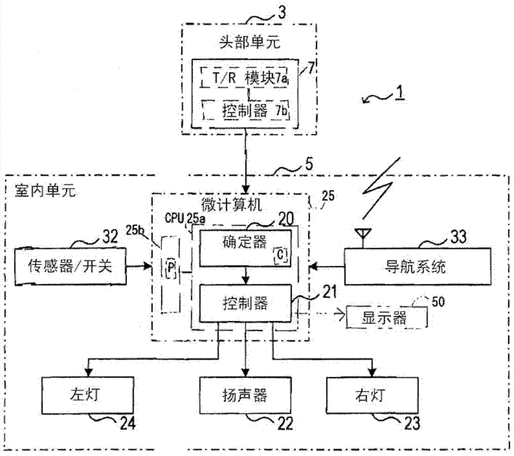
[0050] refer to figure 1 and figure 2 , the driver assistance system 1 includes a head unit 3 and an indoor unit 5 that can communicate with each other. The head unit 3 is placed on the approximate center of the front end (head) of the vehicle V, and the indoor unit 5 is installed inside the vehicle compartment.
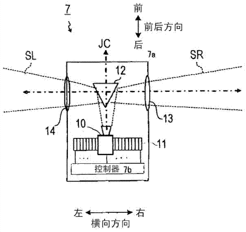
[0051] The head unit 3 includes an object finder 7 . The object finder 7 includes a transmit / receive (T / R) module 7a and a computer 7b. Under the control of the computer 7b, the T / R module 7a emits search waves, such as radar waves, laser waves (laser pulses), ultrasonic waves, etc., to form at least one predetermined search area, and receives signals from those present in the at least one search area. reflected waves from objects. The T / R module 7a then detects objects based on the reflected waves.
[0052] Note...
no. 2 example
[0121] The following will refer to Figure 7 A driver assistance system according to a second embodiment of the present invention is described.
[0122] The structure and / or function of the driver assistance system according to the second embodiment differs from the driver assistance system 1 according to the first embodiment in the warning task performed by the CPU 25a (determinator 20 and controller 21). Therefore, the warning task will be mainly described below.
[0123] In step S150, the CPU 25a (determinator 20) acquires object information from the object searcher 7 at each search cycle of the object searcher 7 when the warning task is started. Next, in step S151 , the CPU 25 a extracts distance information indicating the value of the relative distance between the vehicle V and each object from the object information acquired for each search cycle of the object searcher 7 . Then, in step S152, the CPU 25a monitors how the relative distance between the vehicle V and each...
no. 3 example
[0131] The following will refer to Figure 8 A driver assistance system according to a third embodiment of the present invention is described.
[0132] The structure and / or function of the driver assistance system according to the third embodiment is different from that according to each of the first and second embodiments in that the CPU 25a (determinator 20 and controller 21 ) to execute the warning task. Therefore, the warning task will be mainly described below.
[0133] When executing the warning task, the CPU 25a (determinator 20) performs operations in steps S150 to S160, as with the CPU 25a according to the second embodiment, thereby determining whether the vehicle V is entering the target area.
[0134] That is, the warning task according to the third embodiment does not include the operations in steps S110 to S140 included in the warning task according to the first embodiment. This cancels the determination of whether the vehicle V is going to the target area and ...
PUM
 Abstract
Description
Claims
Application Information
 - R&D
- Intellectual Property
- Life Sciences
- Materials
- Tech Scout
- Unparalleled Data Quality
- Higher Quality Content
- 60% Fewer Hallucinations
Browse by: Latest US Patents, China's latest patents, Technical Efficacy Thesaurus, Application Domain, Technology Topic, Popular Technical Reports.
© 2025 PatSnap. All rights reserved.Legal|Privacy policy|Modern Slavery Act Transparency Statement|Sitemap|About US| Contact US: help@patsnap.com