Stand-up motion assistance robot
A robot and motion technology, applied in medical science, hospital beds, hospital equipment, etc., can solve problems such as complex mechanisms and achieve the effect of simple mechanisms
- Summary
- Abstract
- Description
- Claims
- Application Information
AI Technical Summary
Problems solved by technology
Method used
Image


Examples
no. 1 approach
[0051] Mechanical structure of stand-up action assisting robot
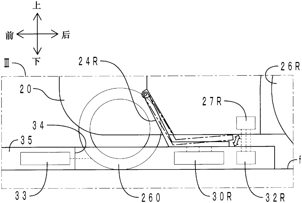
[0052] First, the mechanical structure of the standing motion assisting robot (hereinafter, abbreviated as "robot" as appropriate) of the present embodiment will be described. figure 1 It is a see-through perspective view of the state where the robot main body and the anchor part of the robot of this embodiment are united. figure 2 express figure 1 right side view of . image 3 express figure 2 Enlarged view within Box III of . Figure 4 A block diagram representing the robot.
[0053] Such as Figure 1 ~ Figure 4 As shown, the robot 1 of this embodiment includes a robot main body 2 , an anchor 3 , a shaft side load sensor 40 , a footrest side load sensor 41 , an anchor side control unit 42 , and a main body side control unit 43 . The anchor side control unit 42 and the main body side control unit 43 are included in the concept of the “control unit” in the present invention.
[0054] mainly as figure 1 ...
no. 2 approach
[0114] The stand-up operation assisting robot of the present embodiment differs from the standing operation assisting robot of the first embodiment in that the robot main body does not have a dedicated anchor portion but has a pedal portion. Here, only the differences will be described.
[0115] Figure 6 It is a see-through perspective view showing the robot of this embodiment. Also, for figure 1 Corresponding parts are denoted by the same reference numerals. Such as Figure 6 As shown, the robot main body 2 includes a pair of left and right pedal parts 50L, 50R. The pedal unit 50R includes a pedal body 500R, a first swing shaft 501R, and a second swing shaft 502R. The second swing shaft 502R is protrudingly provided from the right surface of the base 20 . As indicated by arrow Y1, the second swing shaft 502R can swing around its own axis by a second swing motor (not shown). The first swing shaft 501R is mounted on the front end of the second swing shaft 502R. As indi...
no. 3 approach
[0118] The stand-up operation assisting robot of the present embodiment is different from the standing operation assisting robot of the first embodiment in that the robot main body does not have a dedicated anchor but an arm. Here, only the differences will be described.
[0119] Figure 7 It is a see-through perspective view showing the robot of this embodiment. Also, for figure 1 Corresponding parts are denoted by the same reference numerals. Such as Figure 7 As shown, the robot main body 2 includes a pair of left and right arm portions 51L, 51R. The arm portion 51R includes a hand portion 510R, a forearm portion 511R, and an upper arm portion 512R. As indicated by arrow Y3 , the upper end of the upper arm portion 512R is attached to the right surface of the base portion 20 in a swingable manner. As indicated by arrow Y4, the rear end of the forearm portion 511R is swingably attached to the lower end of the upper arm portion 512R. The hand 510R includes a palm 510Ra ...
PUM
 Abstract
Description
Claims
Application Information
 - Generate Ideas
- Intellectual Property
- Life Sciences
- Materials
- Tech Scout
- Unparalleled Data Quality
- Higher Quality Content
- 60% Fewer Hallucinations
Browse by: Latest US Patents, China's latest patents, Technical Efficacy Thesaurus, Application Domain, Technology Topic, Popular Technical Reports.
© 2025 PatSnap. All rights reserved.Legal|Privacy policy|Modern Slavery Act Transparency Statement|Sitemap|About US| Contact US: help@patsnap.com