
Ear pad

A technology for ear pads and earphones, which is applied to earpieces/headphone accessories, on-ear/over-ear earphones, sensors, etc., can solve problems such as user discomfort, high air tightness, poor air permeability, and humidity of ear pads

Inactive Publication Date: 2012-08-01
SONY CORP
View PDF5 Cites 8 Cited by
  • Summary
  • Abstract
  • Description
  • Claims
  • Application Information

AI Technical Summary

Problems solved by technology

[0004] However, on the other hand, the high airtightness of the ear pads can also result in poor air permeability
As a result, when an earphone having such highly airtight ear pads is used for a long time, the periphery of the ear and the user's temporal region become wet, thereby causing discomfort to the user.

Method used


Image

  • Ear pad
  • Ear pad
  • Ear pad

Examples


Embodiment Construction

[0017] Hereinafter, embodiments of the present invention are described with reference to the drawings. However, the present invention is not limited to the following examples. Descriptions are given in the following order.

[0018] 1. Example

[0019] 1-1. Structure of earphones

[0020] 1-2. Structure of ear pads

[0021] 2. Modify

[0022] 1. Example

[0023] 1-1. Structure of earphones

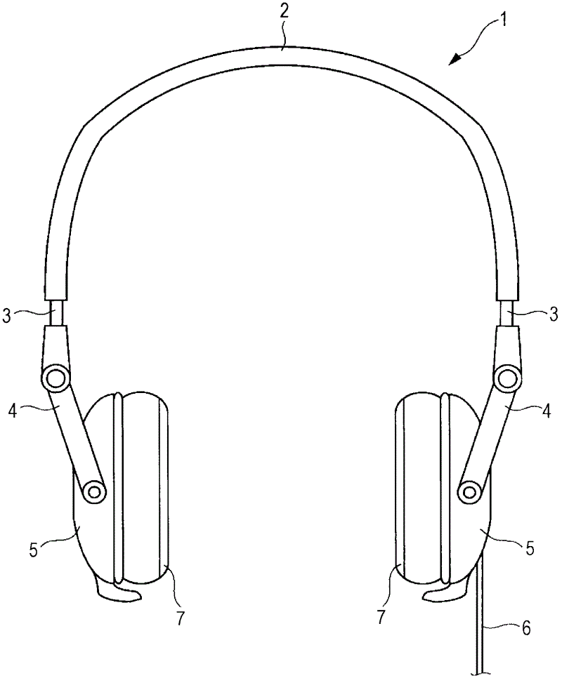
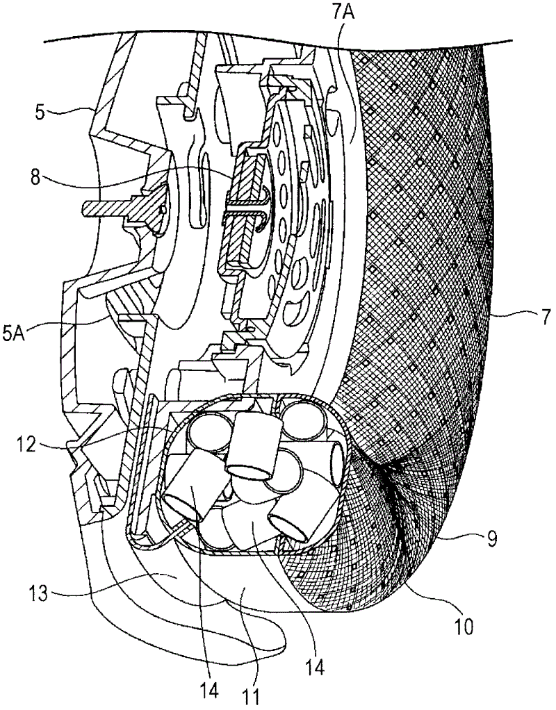
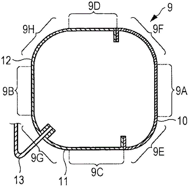
[0024] First, refer to figure 1 and Figures 2A to 2C Describe the construction of the earphone. figure 1 is a diagram showing the external configuration of the earphone 1 having the earpad 7 according to the embodiment of the present invention. Figure 2A It is a cross-sectional perspective view of the housing 5 and the ear pad 7 on the R channel side of the earphone 1 . Figure 2B is a side sectional view of the outer body 9 constituting the earpad. The housing 5 and ear pads 7 on the L channel side are similar in construction to the housing and ear pads on the R channel side. ...


PUM


Abstract

An ear pad includes an exterior body which is mounted on a headphone and is formed in a ring shape having a hollow internal space, at least a contact surface of the exterior body with a user's temporal region having air permeability when the headphone is worn; and air permeable members placed in the exterior body.

Description

technical field [0001] The present technology relates to ear pads, and in particular, to ear pads provided in earphones and the like as cushioning members. Background technique [0002] Heretofore, headphones have been used to listen to sound output from various sound reproduction devices such as music players and television receivers. Headphones generally include a headband to be brought into contact with a user's head and a pair of housings for accommodating sound output devices including a driver unit and the like, the housings being provided at respective left and right ends of the headband. In addition, on the side of each housing facing the temporal region of the user's head, ear pads are provided as cushioning members that prevent the housing from coming into direct contact with the temporal region. [0003] The ear pad serves as a cushioning member that reduces a user's uncomfortable feeling due to contact between the user's ear, temporal region, and the earphone wh...

Claims


Application Information

Patent Timeline
IPC IPC(8): H04R1/10
CPCH04R1/10H04R1/1008H04R1/1091
Inventor 西原弘和筱原几夫
Owner SONY CORP
Learn More