Eureka AIR delivers breakthrough ideas for toughest innovation challenges, trusted by R&D personnel around the world.
Haulage winch
What is Al technical title?
Al technical title is built by PatSnap Al team. It summarizes the technical point description of the patent document.
A winch and reel technology, applied in the direction of the hoisting device, the spring mechanism, etc., can solve the problems of small operating space, limited field of vision, and small axial operating distance for workers, and achieve convenient operation, improve operating environment, and operating space. increased effect
Active Publication Date: 2014-11-26
TRIUMPH HEAVY IND
View PDF6 Cites 0 Cited by
Summary
Abstract
Description
Claims
Application Information
AI Technical Summary
This helps you quickly interpret patents by identifying the three key elements:
Problems solved by technology
Method used
Benefits of technology
Problems solved by technology
like figure 1 The shown safety brake 14 is installed on one side close to the motor 11, and the two working brakes 13 are placed on the other side of the motor 11. The position of the operating handle 15 is as follows: figure 1 As shown, it is very close to the working brake 13, because the diameter of the brake wheel 17 and the diameter of the drum baffle 16 are relatively large, the radial distance to the handle 15 is small, and because the distance between the two brake wheels Closer, so that the axial operating distance of the two operating handles 15 is also smaller, the operating space for workers is too small, and the field of vision is limited
Method used
Image
Click on the blue label to locate the original text in one second.
Reading with bidirectional positioning of images and text.
Examples
Embodiment Construction
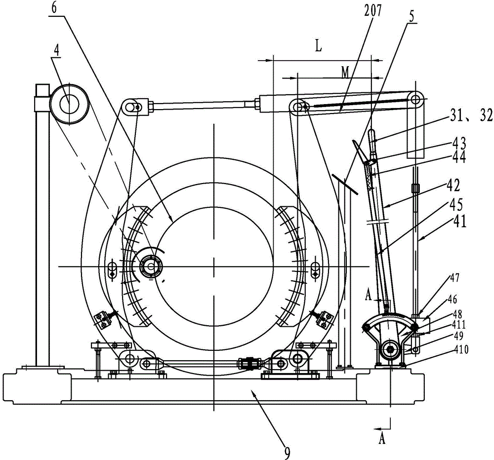
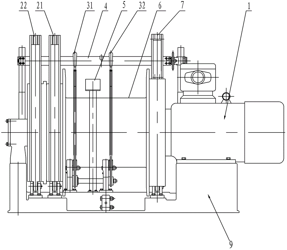
[0028] Such as figure 2 , 3 As shown, the transportation winch of the present invention includes a base 9, a motor 1, a reduction transmission system, a reel 6, a braking device, an operating device, a depth indicator 4, and a console 5. The base is designed in a symmetrical structure, and the motor is installed on the base 9 On the right, the output shaft of the motor is connected to the reel through a reduction drive system, which is set inside the reel.
[0029] Combine Figure 4 As shown, the reduction transmission system includes a primary planetary gear reduction mechanism 122, a secondary planetary gear reduction mechanism 123, and a lubrication system. One end of the output shaft 151 of the motor 1 extending into the reel 6 is equipped with a primary planetary gear reduction mechanism 122, and the planet carrier of the primary planetary gear reduction mechanism 122 is connected to the output shaft 124 of the secondary planetary gear reduction mechanism 123 through a gear ...
PUM
Abstract
The invention discloses a haulage winch which comprises a base, a motor, a decelerating transmission system, a winding drum, a braking device, an operating device, a depth indicator and a console, wherein the motor is mounted on the right side of the base, the output shaft of the motor is connected with the winding drum through the decelerating transmission system, the decelerating transmission system is arranged inside the winding drum, the braking device comprises a first brake wheel, a second brake wheel, a first work brake, a second work brake, and a safety brake, the console is fixed on the base in front of the winding drum, the operating device comprises a first operating handle and a second operating handle, the first operating handle is used for controlling the brake of the first brake, the second operating handle is used for controlling the brake of the second brake, the depth indicator is mounted above the rear side of the winding drum, the two operating handles are respectively mounted on the base in front of the control console and positioned on the left and the right sides of the console, the radial distance between each operating handle and the winding drum is set to be L, the radial distance between each operating handle and each brake drum is M, and the L is larger than the M.
Description
Technical field [0001] The invention relates to a transportation equipment, in particular to a transportation winch. Background technique [0002] The working principle of the transport winch is to provide torque to the drum 12 through the motor 11 through the reducer system, use the steel wire rope to wind the drum, and the brake device to control the operation and stop of the drum to meet the purpose of dispatching and transporting materials. In order to make the winch compact, the deceleration system is usually placed in the drum, and the motor shaft extends into the drum; to ensure the safety and reliability of the winch, the winch is designed with three brake devices, two of which are working brakes 13, and one is Safety brake 14, one of the working brakes is used for separation. The safety brake is controlled by a hydraulic brake, and the working brake is operated manually. Such as figure 1 The safety brake 14 shown is installed on the side close to the motor 11, and the ...
Claims
Application Information
Patent Timeline
Application Date:The date an application was filed.
Publication Date:The date a patent or application was officially published.
First Publication Date:The earliest publication date of a patent with the same application number.
Issue Date:Publication date of the patent grant document.
PCT Entry Date:The Entry date of PCT National Phase.
Estimated Expiry Date:The statutory expiry date of a patent right according to the Patent Law, and it is the longest term of protection that the patent right can achieve without the termination of the patent right due to other reasons(Term extension factor has been taken into account ).
Invalid Date:Actual expiry date is based on effective date or publication date of legal transaction data of invalid patent.