
Variable displacement scroll compressor

A scroll compressor, variable displacement technology, applied in the direction of rotary piston machinery, mechanical equipment, machine/engine, etc., can solve the problems of refrigerant leakage, reduction of compressor compression efficiency, inappropriate compression, etc.

Inactive Publication Date: 2012-05-23
DENSO CORP
View PDF5 Cites 1 Cited by
  • Summary
  • Abstract
  • Description
  • Claims
  • Application Information

AI Technical Summary

Problems solved by technology

[0006] In such a variable displacement type scroll compressor, the compression of the refrigerant in the variable displacement operation mode is not moderate (ie, abrupt), and therefore, the refrigerant in each compression chamber may leak from the compression chamber As a result, when the compressor operates in variable displacement operation mode, the compression efficiency of the compressor is reduced

Method used


Image

  • Variable displacement scroll compressor
  • Variable displacement scroll compressor
  • Variable displacement scroll compressor

Examples


no. 2 example

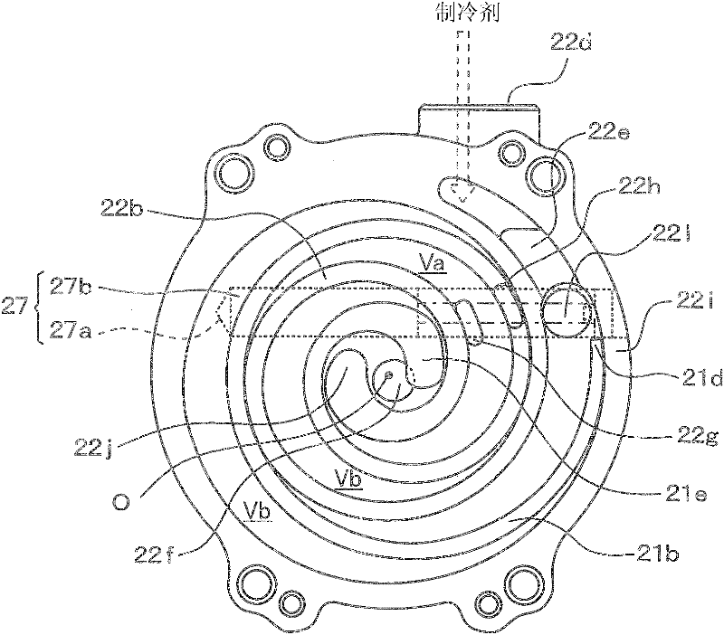
[0115] Then refer to Figures 13A to 13D A second embodiment of the present invention is described. said Figures 13A to 13D is an explanatory diagram for describing the operation of the compressor 10 of the present embodiment. said Figures 13A to 13D Corresponding to the first embodiment respectively Figures 9A to 9D .

[0116] In the first embodiment, the main bypass port 22h is located at a position where the first imaginary line L1 and the third imaginary line L3 coincide, and the secondary bypass port 22h and the main bypass port 22g are formed as independent holes. On the contrary, unlike the first embodiment, according to the present embodiment, the sub bypass port 22h and the main bypass port 22g are formed as a common single hole. In this embodiment, descriptions of components similar to those in the first embodiment will be omitted or simplified.

[0117] In this example, as in Figures 13A to 13D As shown in , an annular hole is formed at a position shifte...

no. 3 example

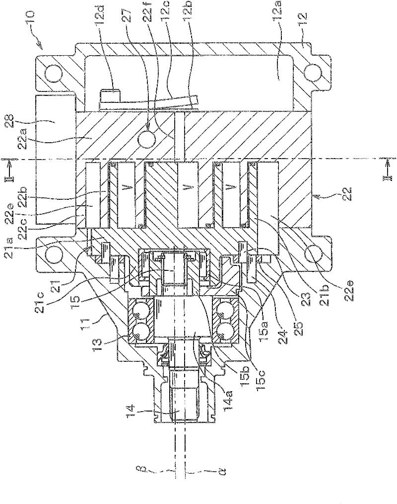
[0122] Refer below Figures 14 to 15 A third embodiment of the present invention is described. Figure 14 is a longitudinal sectional view of the compressor 10 of this embodiment, Figure 15 yes Figure 14 The sectional view seen along the line XV-XV in the middle.

[0123] The compressor 10 of this embodiment differs from the compressor 10 of either of the first or second embodiments in the following points. That is, unlike in the first and second embodiments, in this embodiment, the volume of the radially outer compression chamber V located on the radially outer side of the scrolls 21, 22 is larger than the volume of the radially outer compression chamber V located on the scrolls 21, 22. The volume of the radially inner compression chamber V on the radially inner side. In this embodiment, descriptions of components similar to those in the first embodiment will be omitted or simplified.

[0124] Such as Figure 14 and 15 As shown, in this embodiment, a step 22m is form...


PUM


Abstract

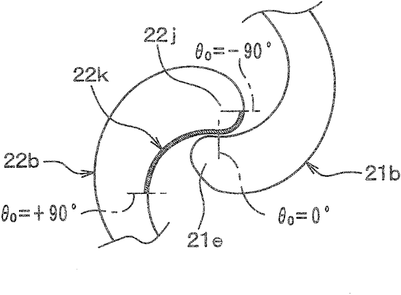
A stationary base plate includes a sub-bypass hole, which communicates between a suction chamber and a first compression chamber, and a main bypass hole, which communicates between the suction chamber and a second compression chamber. A rotational center of the orbiting scroll and the sub-bypass hole are located along a first imaginary line. The rotational center of the orbiting scroll is also located along a second imaginary line, which is perpendicular to the first imaginary line. The main bypass hole opens at a location of the stationary base plate, which is on a side of the second imaginary line where the sub-bypass hole is located, so that timing of communicating between the suction chamber and the first compression chamber with each other is deviated from timing of communicating between the suction chamber and the second compression chamber with each other.

Description

technical field [0001] The invention relates to a variable displacement scroll compressor. Background technique [0002] For the scroll compressor known in the prior art, the fixed scroll and the movable scroll are in contact with each other, and the refrigerant flows in the two closed spaces (compression chambers) respectively defined by the above fixed scroll and movable scroll. ) are compressed. In this scroll compressor, the movable scroll rotates a plurality of times (for example, twice) relative to the fixed scroll so that refrigerant sucked into each compression chamber is compressed. The compression of the refrigerant in the scroll compressor is more moderate compared to the piston compressor, so the leakage of refrigerant from each compression chamber is less in the scroll compressor. [0003] One known such scroll compressor is a variable displacement scroll compressor (for example, see JPS59-028083A, corresponding to US4505651A). In known variable displacement ...

Claims


Application Information

Patent Timeline
Patent Type & Authority Applications(China)
IPC IPC(8): F04C18/02
CPCF04C18/0276F04C18/0261F04C28/26
Inventor 川野茂佐贯政美石原孝宏
Owner DENSO CORP
Learn More