
Hair transplanting device

A hair-planting device and a hair-planting needle technology, applied in the field of hair-planting devices, can solve the problems of uncontrollable management, assembly consumption, inconvenient operation, etc., and achieve the effect of shortening the insertion and installation time, convenient insertion method, and easy management.

Inactive Publication Date: 2012-04-11
韩士生科有限公司
View PDF4 Cites 4 Cited by
  • Summary
  • Abstract
  • Description
  • Claims
  • Application Information

AI Technical Summary

Problems solved by technology

However, the existing hair transplanter is a cylindrical pen-shaped hair transplanter, so the operator needs to find the direction of the gap while rotating the hair transplanter.
[0011] Moreover, when the operator places the hair transplanter on the operation table during the non-operative period, since the hair transplanter is cylindrical, there is a defect that it is easy to roll and fall to the ground or cannot be managed normally.
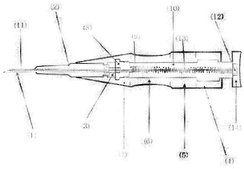
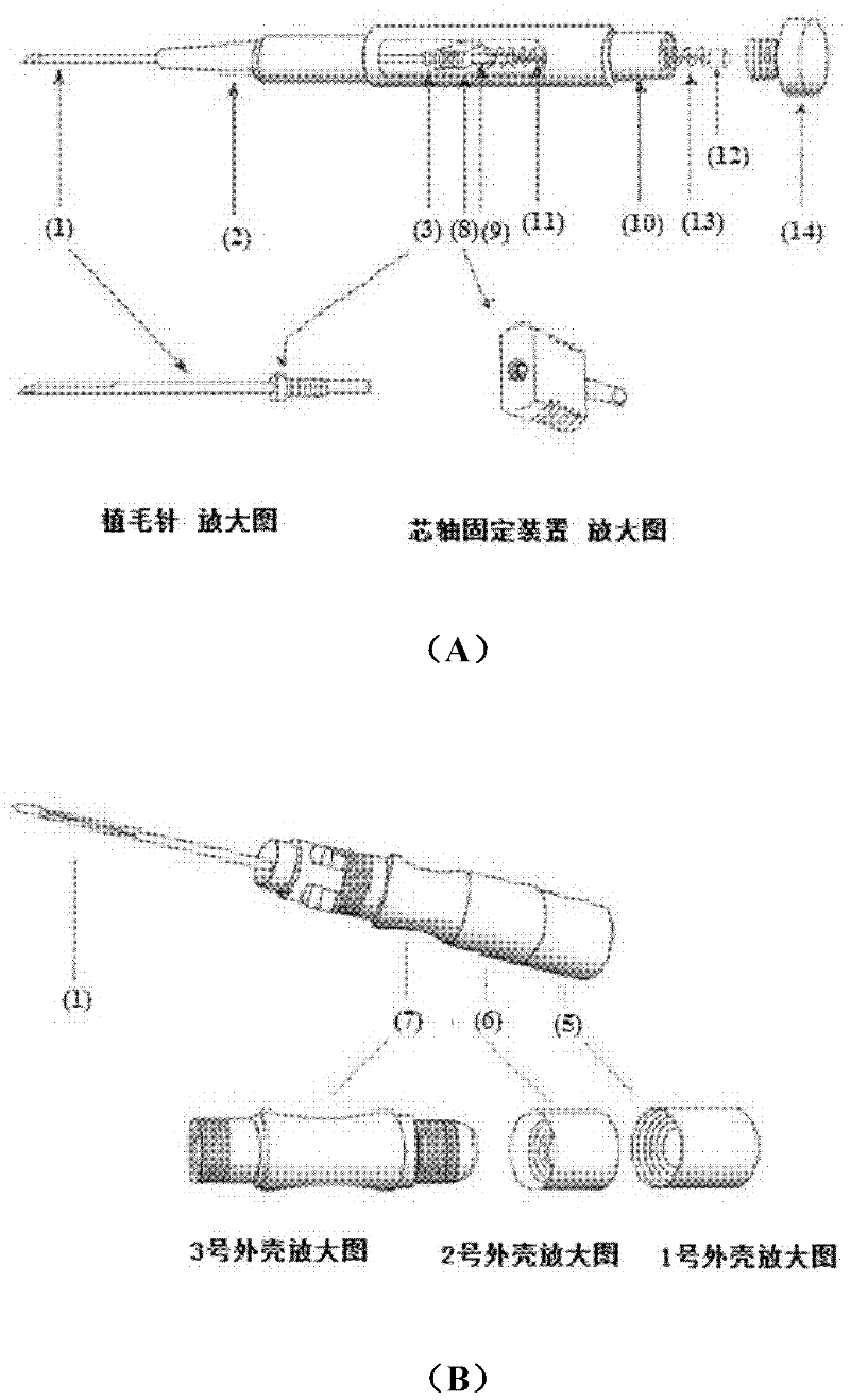
[0012] In addition, when the existing hair transplanter is assembled after separation, such as figure 2 As shown in part (A) of d, the above-mentioned mandrel fixing device needs to be inserted into the position where the guide hole is formed on the side of the mandrel support, and the hair-planting needle needs to be inserted into the above-mentioned mandrel fixing device, so there is too much time for assembly , the defect that the operation is quite inconvenient

Method used


Image

  • Hair transplanting device
  • Hair transplanting device
  • Hair transplanting device

Examples


Embodiment Construction

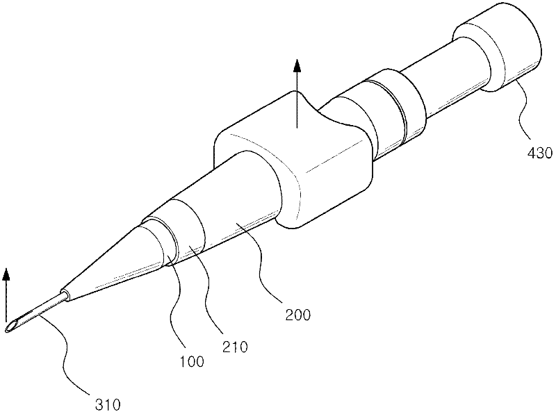
[0031] image 3 It is a perspective view of the hair transplanter of the embodiment of the present invention, Figure 4 It is the separation and assembly drawing of the hair transplanter structure of the present invention. Such as image 3 and Figure 4 As shown, the hair transplanter includes: a mandrel supporting shell 100, which is in the shape of a hollow pen, and a guide hole is formed along the length direction of its main body; a mandrel holder 300, which is inserted into the above-mentioned guide hole, can Carry out linear motion, and be formed with the cap fixing part 305 that protrudes from the top of the guide hole; Hair transplanting needle 310, it is attached and inserted in the above-mentioned mandrel holder 300 with the vertical direction of the above-mentioned cap fixing part 305 and the vertical direction of the slit; A cylindrical fixed case 200 wraps the main body of the mandrel support case 100, and a hole 205 corresponding to the cover fixing part 305 i...


PUM


Abstract

The present invention relates to a hair transplanting device which transplants the roots of hair in skin. The hair transplanting device comprises: a core shaft support case (100) which has a hollow pen shape and has a guide hole formed in the longitudinal direction of a body; a core shaft fixer (300) which is inserted into the guide hole to enable linear movement along the guide hole, and has a cap fixing portion (305) protruded above the guide hole; a hair transplanting needle (310) which is adhered to and inserted into the core shaft fixer (300) in accordance with the vertical direction of the cap fixing portion (305) and the vertical direction of a slit; a cylindrical fixing case (200) which encompasses the body of the core shaft support case (100) and has a hole (205) corresponding to the cap fixing portion (305) at the central portion thereof; a core shaft unit (300) which is inserted into the support case (100) and has a core shaft cap at the end portion thereof; a spring (450) which enables linear movement through elastic force between the core shaft fixer (300) and the core shaft unit (300); and a core shaft fixing cap (350) which is inserted into the hole and the cap fixing portion (305) of the core shaft fixer (300) at the upper portion of the fixing case (200). The present invention provides advantages of remarkably reducing the assembling time for operation, making the assembling method more convenient and simple, and allowing easy use by an operator. Furthermore, the present invention has advantages of allowing an operator to find a slit direction easily, and providing easy maintenance because the fixing cap prevents a hair transplanting device from rolling around when an operator puts the hair transplanting device on an operating table.

Description

technical field [0001] The invention relates to a hair transplanter for implanting hair into the skin, and in more detail relates to a hair transplanter which is convenient for operation, can shorten assembly time, and is easy to manage. Background technique [0002] The present invention relates to a hair transplanter for transplanting hair to a depilatory site. More specifically, it relates to a device that can conveniently adjust the hair transplantation when inserting the hair root according to the different thicknesses of skin tissue layers in the scalp of different people when transplanting hair. The hair transplanter with the length of the needle can prevent the damage of the skin tissue in the scalp in advance, so that the hair root can be stably implanted in the scalp, and push the hair root into the scalp, so as to prevent the hair part of the hair root from being brought into the hair transplant needle , so that the time for hair transplantation can be shortened. ...

Claims


Application Information

Patent Timeline
IPC IPC(8): A61F2/10A61B17/03
CPCA61B17/3468A61B2017/00752A61B17/00A61F2/10
Inventor 权元均
Owner 韩士生科有限公司
Learn More