Energy-saving alternating-current contactor with fault clearing lock

A technology for AC contactors and contactors, applied in the direction of relays, electromagnetic relays, detailed information of electromagnetic relays, etc., can solve the problems of contactor coils consuming electric energy, consuming a lot of manpower and resources, and the coils are easy to be burned and damaged, so as to save electric energy and Effects of resources, huge economic and social benefits

Inactive Publication Date: 2012-04-11
张汉全
View PDF4 Cites 6 Cited by
  • Summary
  • Abstract
  • Description
  • Claims
  • Application Information

AI Technical Summary

Problems solved by technology

One of its defects is that the contactor coil consumes electric energy. According to estimates, the country loses more than 7 billion kilowatt-hours of electric energy every year for this reason; the second defect is that the contactor coil is charged for a long time, and the coil is easily burned and damaged. Frequent replacement and maintenance consumes a lot of manpower and resources. In addition, when the circuit has a short circuit, open fault, etc., the existing AC contactor itself will not automatically disconnect and lacks automatic protection functions.

Method used


Image

  • Energy-saving alternating-current contactor with fault clearing lock
  • Energy-saving alternating-current contactor with fault clearing lock
  • Energy-saving alternating-current contactor with fault clearing lock

Examples


Embodiment 1

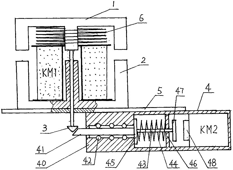
[0035] Such as figure 1 As shown, the mountain-shaped static iron core 2 covered with the contactor coil KM1 is fixed on the support plate 5 with the opening facing upward, the supporting spring 6 makes the moving iron core 1 above the static iron core 2, and the three-phase moving contact Q 1 , Q 2 , Q 3 The upper end of the shaft of the lock hook 3 is fixed in the center below the moving iron core 1 in a linkage manner, and the shaft passes through the center hole of the static iron core 2 and the through hole on the support plate 5 to support The below plate 5 is equipped with a fault-removing lock 4, and the dead bolt bar 41 head of the fault-removing lock 4 is close to the iron hook 3 center line.

[0036] The structure of the mechanical part of the fault-removing lock 4 is as follows: a deadbolt bar 41 and a ball 42 are installed in the groove center hole of the front portion of the lock body 40, and a back-moving spring 44 is set on the connecting rod 43 in the cavity...

Embodiment 2

[0039] This embodiment is basically the same as example one, except that the structure of the electrical part of the fault-removing lock 4 is as follows: Figure 5 As shown, it is exactly the same as the second technical solution described above, and will not be repeated here.

Embodiment 3

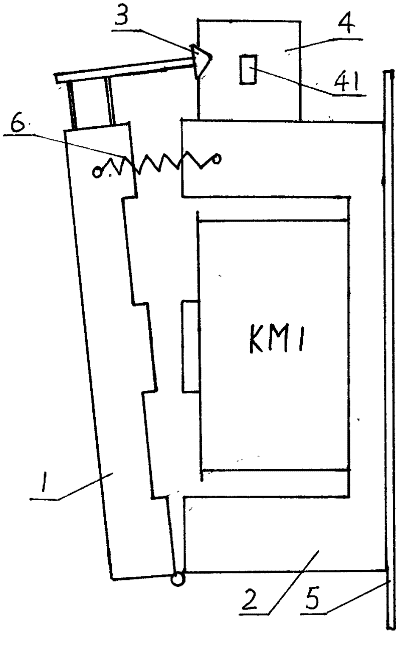
[0041] Such as figure 2 As shown, the mountain-shaped static iron core 2 covered with the contactor coil KM1 opens to one side and is fixed on the support plate 5. The inner and lower ends of the moving iron core 1 and the static iron core 2 are hinged to each other. The three-phase moving contact Q 1 , Q 2 , Q 3 It is solidly connected with the moving iron core 1 in a linkage manner, the shaft of the lock hook 3 is fixed above the moving iron core 1, the fault-removing lock 4 is fixed above the static iron core 2, and the head of the deadbolt rod 41 of the fault-removing lock is close to the The lock hook 3 center lines that are in a horizontal state are equipped with support springs 6 between the dynamic and static iron cores. In the present embodiment, the structure of the fault lock 4 is exactly the same as the example one.


PUM


Abstract

The invention relates to an energy-saving alternating-current contactor with a fault clearing lock. A lock hook is fixedly mounted on a moving iron core; the fault clearing lock is mounted below or above a static iron core; and the head of a lock tongue stem of the fault clearing lock is adjacent to a center line of the lock hook. A connecting rod on which a reset spring is sleeved is arranged ina lock body, the front end of the connecting rod is fixedly connected with a lock tongue stem baffle, and the rear end of the connecting rod is fixedly connected with an iron absorption plate; an unlocking coil and an iron core are mounted in a rear cavity of the lock body; and the unlocking coil is connected with an open-phase and short-circuit fault automatic clearing circuit. The invention hasthe characteristics that the mechanical self-locking of the three-phase moving contact can be realized, so that the coil of the contactor is uncharged during the normal operation to prolong the service life of the coil of the contactor and save the electric energy and the resources; when the faults of open phase and short circuit exist in an electric line, a switch is automatically closed to power off, so that the economic benefit and the social benefit are huge.

Description

technical field [0001] The invention relates to an electrical switchgear for controlling the switching on and off of a three-phase circuit or a three-phase electrical appliance, in particular to an automatic protection switchgear capable of automatically clearing open-phase and short-circuit faults. Background technique [0002] In various existing three-phase circuits, relay self-locking devices are used. When the start button switch is pressed and then disconnected, the self-locking device continues to keep the contactor coil energized to ensure that the three-phase moving contacts of the AC contactor are in a closed state. That is, the contactor coil must be energized for proper operation. One of its defects is that the contactor coil consumes electric energy. According to estimates, the country loses more than 7 billion kilowatt-hours of electric energy every year for this reason; the second defect is that the contactor coil is charged for a long time, and the coil is e...

Claims


Application Information

Patent Timeline
IPC IPC(8): H01H50/16H01H50/64
Inventor 张汉全
Owner 张汉全
Why Eureka
Try Eureka