Measurement reference signal transmission method and device
A technology for measuring reference signals and control information, which is applied in the field of communication, and can solve problems such as unproposed solutions, asymmetric configuration of transmitting and receiving antennas, and inability to judge when
- Summary
- Abstract
- Description
- Claims
- Application Information
AI Technical Summary
Problems solved by technology
Method used
Image
Examples
example 1
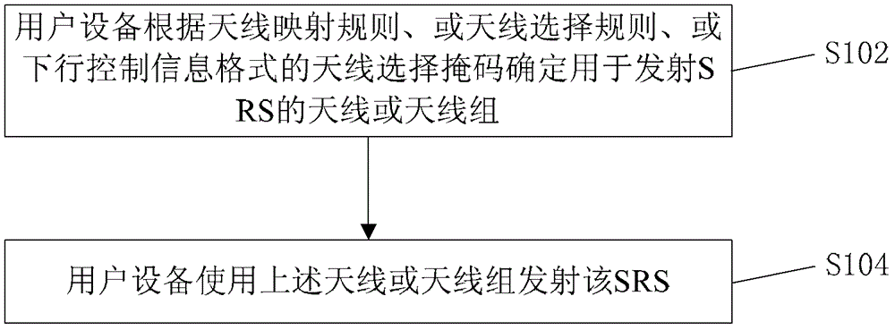
[0078] In this example, the user equipment selects an antenna or an antenna group to transmit the measurement reference signal according to an antenna mapping rule.
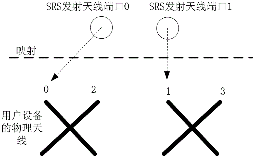
[0079] Such as figure 2 As shown, when the number of uplink SRS transmit antennas is 2 and the number of downlink receive antennas is 4, in order to solve some channel reciprocity problems, the SRS transmit antenna ports can be switched and mapped between physical transmit antennas in sequence at different SRS transmission times . For example, in the first transmission subframe of the SRS, the transmission port 0 of the SRS is mapped to the physical antenna 0, and the transmission port 1 of the SRS is mapped to the physical antenna 1; then in the second transmission subframe of the SRS, the transmission port 0 of the SRS Mapped to physical antenna 2, SRS transmit port 1 is mapped to physical antenna 3; in the third transmit subframe of SRS, SRS transmit port 0 is mapped to physical antenna 0, and SRS transmit p...
example 2
[0084] In this example, the user equipment selects an antenna or an antenna group to transmit the measurement reference signal according to an antenna selection rule.
[0085] The above antenna selection rules include:
[0086] The UE is at antenna index or group index a(n SRS ) on the antenna or group of antennas to transmit the nth SRS measurement reference signals, where each set of transmit antennas includes one or more transmit antennas, and the antenna index or antenna group index a(n SRS ) is determined as follows:
[0087] method one:
[0088] a(n SRS ) = n SRS mod2 or a(n SRS ) = n SRS mod4.
[0089] Method 2:
[0090] When SRS frequency hopping in the frequency domain is not enabled, a(n SRS ) = n SRS mod2 or a(n SRS ) = n SRS mod4;
[0091] When SRS frequency hopping in the frequency domain is enabled,
[0092]
[0093]
[0094] or
[0095] in is 1, N b′ The number of branches corresponding to layer b' when assigning the SRS bandwidth ...
example 3
[0098] In this example, the user equipment determines the antenna or antenna group to transmit the measurement reference signal according to the antenna selection mask in the downlink control information format.
[0099] The format of the downlink control information has a one-to-one correspondence with the antenna (port) of the user equipment or with the antenna (port) group, and the antenna (port) group includes one or more antennas (ports).
[0100] The downlink control information format is an information format that bears uplink scheduling information or bears downlink scheduling information, and the downlink control information formats include: format 4, format 2A, format 2B, and format 2C.
[0101] When the base station transmits multiple PDCCHs carrying antenna selection masks to the user equipment in a certain subframe, the base station may carry the same antenna selection mask on the multiple PDCCHs or the base station may carry the same antenna selection mask on one ...
PUM
 Abstract
Description
Claims
Application Information
 - Generate Ideas
- Intellectual Property
- Life Sciences
- Materials
- Tech Scout
- Unparalleled Data Quality
- Higher Quality Content
- 60% Fewer Hallucinations
Browse by: Latest US Patents, China's latest patents, Technical Efficacy Thesaurus, Application Domain, Technology Topic, Popular Technical Reports.
© 2025 PatSnap. All rights reserved.Legal|Privacy policy|Modern Slavery Act Transparency Statement|Sitemap|About US| Contact US: help@patsnap.com


