
Device and method for evaluating displacement capability of wetting phase of rock at high temperature under high pressure

A high-temperature, high-pressure, wetting phase technology, applied in the field of petroleum industry, can solve the problems of not considering the influence of temperature and pressure effects on the displacement efficiency of wetting phase, the inability to simulate the reservoir environment, and experimental errors, so as to achieve true and reliable experimental conditions , strong operability and reliable principle

Inactive Publication Date: 2013-10-09
SOUTHWEST PETROLEUM UNIV
View PDF6 Cites 0 Cited by
  • Summary
  • Abstract
  • Description
  • Claims
  • Application Information

AI Technical Summary

Problems solved by technology

[0004] (1) Existing experimental methods for evaluating the displacement capacity of wetting phases are mainly aimed at normal temperature and pressure environments, without considering the influence of temperature and pressure effects on the displacement efficiency of wetting phases, that is, they cannot simulate the real underground reservoir environment
[0005] (2) In order to meet the visualization requirements of the existing experimental device, the material of the device is made of glass, but the glass material cannot withstand excessive pressure
[0006] (3) The traditional experiment time is too long, because the precipitated oil adheres to the surface of the core and is difficult to detach, so the deoiling can only be achieved through a vibration device, which will inevitably cause experimental errors

Method used


Image

  • Device and method for evaluating displacement capability of wetting phase of rock at high temperature under high pressure
  • Device and method for evaluating displacement capability of wetting phase of rock at high temperature under high pressure
  • Device and method for evaluating displacement capability of wetting phase of rock at high temperature under high pressure

Examples


Embodiment Construction

[0040] Further illustrate the present invention below in conjunction with accompanying drawing.

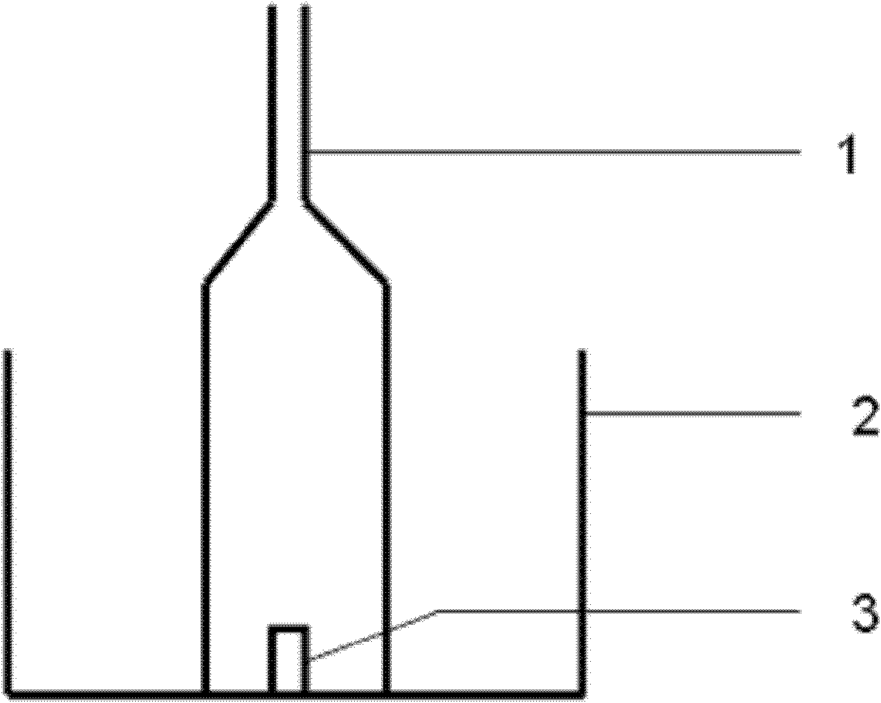
[0041] See figure 1 . figure 1 It is a traditional displacement measurement device, and the simulated injection water is placed in the glass tank 2; the core 3 is placed in the center of the tank, so that the core is completely immersed in the water in the simulated injection water environment; the glass cover 1 is put into the tank and the core Surrounded, and then start the water flooding experiment, the separated oil will automatically enter the upper part of the glass cover under the action of gravity, so as to record the amount of oil produced.

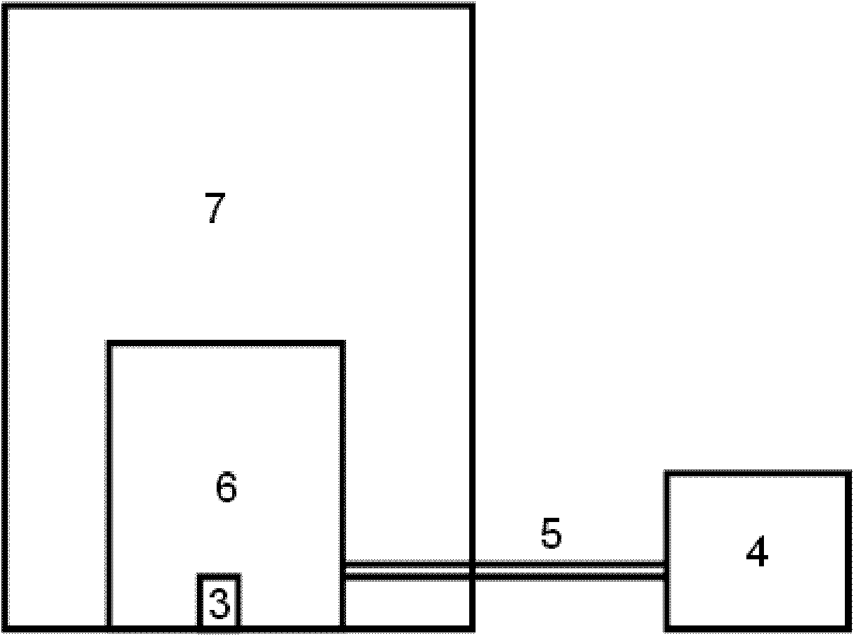
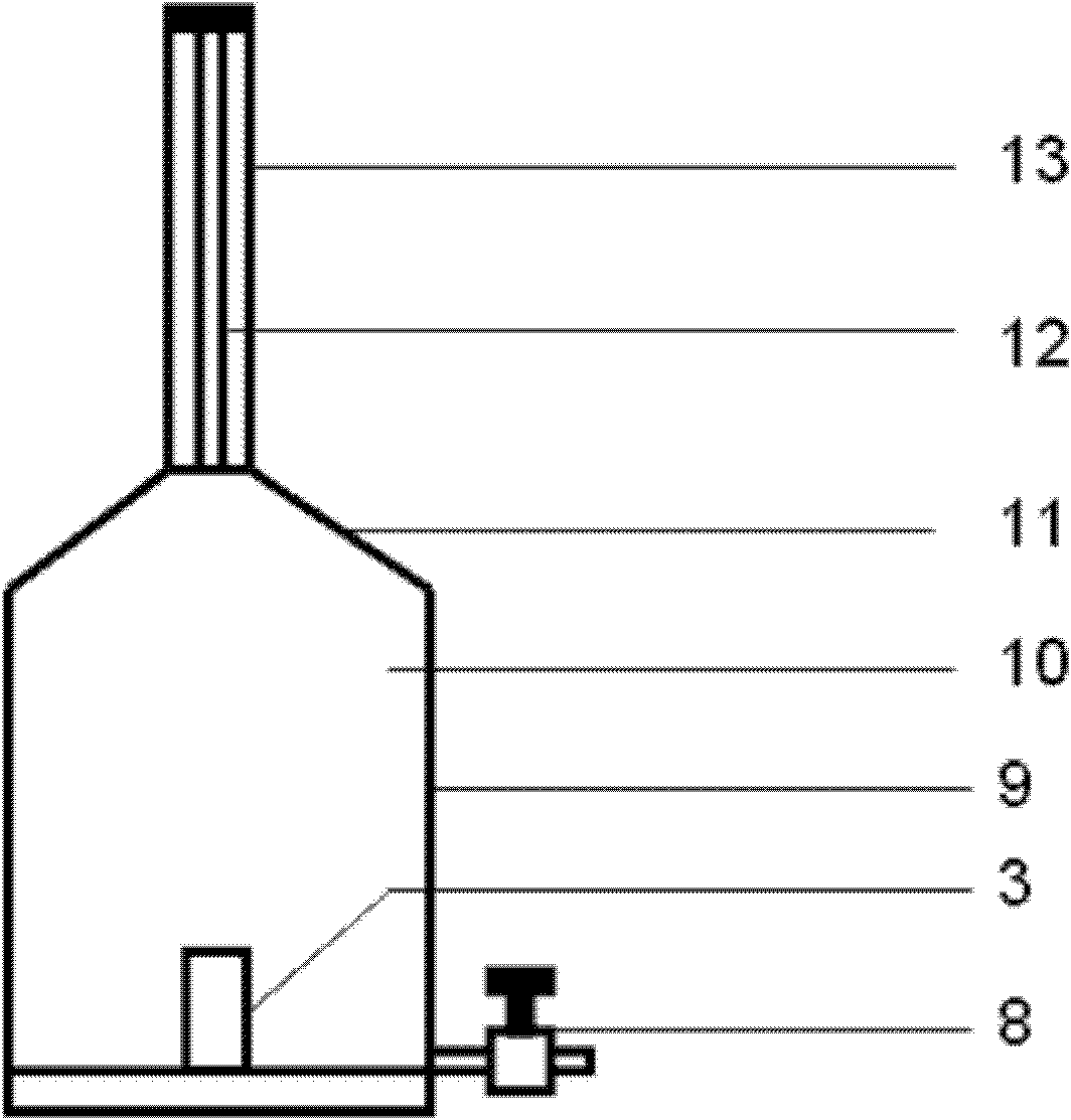
[0042] See figure 2 , image 3 .

[0043] A device for evaluating the displacement ability of rock wetting phase under high temperature and high pressure, mainly composed of a displacement device 6, a constant temperature box 7 and a pressure pump 4, the displacement device is located in the temperature control box, and the disp...


PUM


Abstract

The invention relates to a device and a method for evaluating the displacement capability of a wetting phase of a rock at high temperature under high pressure. The device mainly consists of a displacing device, a thermostat and a pressure pump. The displacing device is positioned in the thermostat and consists of a core chamber, a cone channel and a measurement part. The core chamber is a steel cylinder. A core is placed in the steel cylinder. The bottom of the core chamber is provided with a liquid inlet with a valve. The liquid inlet is connected with the pressure pump outside the thermostat. The measurement part consists of a thick wall glass tube with scales and a steel bushing which is positioned outside the glass tube and is provided with a hole. The core chamber is connected with the measurement part through the cone channel. The device has reliable principle, is simple and convenient to operate and has strong practicality. Not only can the real underground high-temperature and high-pressure oil accumulation environment be simulated, but also the effects of ensuring oil to be rapidly separated from the surface of the core and accurately reading out the oil output are realized, an effectively evaluation approach is provided for the displacement efficiency of the wetting phase in the environment of high temperature and high pressure, and the reliable basis is provided for guiding the site to design a reasonable injection-production scheme.

Description

technical field [0001] The invention relates to the field of petroleum industry, an experimental device and method for evaluating the ability of a core wetting phase to displace a non-wetting phase in a high temperature and high pressure environment during oil and gas field development. Background technique [0002] The wetting phase displacing the non-wetting phase describes the mass transfer phenomenon between the fracture and the matrix. The wetting phase, as a displacement force, is the main oil displacement mechanism in the water injection development process. The displacement capacity of the wetting phase is low. The production of crude oil is determined in the development of permeable tight fractured reservoirs (water is the wetting phase and oil is the non-wetting phase). However, in the actual oilfield water injection development process, there is no way to know what water injection volume and water injection speed can achieve the most efficient oil and gas recovery...

Claims


Application Information

Patent Timeline
Patent Type & Authority Patents(China)
IPC IPC(8): E21B43/20E21B47/00
Inventor 刘向君戴岑璞叶仲斌王森陈一键刘洪
Owner SOUTHWEST PETROLEUM UNIV
Learn More