
Multi-function line pole machine

A pole machine, multi-functional technology, applied in building types, buildings, towers, etc., can solve the problems of low construction efficiency, high labor intensity, and difficulty in improving work efficiency, and achieve low labor intensity for workers, high construction efficiency, and ease of use. effect of operation

Active Publication Date: 2011-12-28
HENAN POWER TRANSMISSION & TRANSFORMATION CONSTR CO LTD +2
View PDF3 Cites 16 Cited by
  • Summary
  • Abstract
  • Description
  • Claims
  • Application Information

AI Technical Summary

Problems solved by technology

[0002] In the construction of power transmission lines, erecting cement poles is an important step. In the process of erecting poles, drilling holes from the ground, erecting poles, and erecting them into the holes requires many people to complete this series of work, which requires a lot of labor. High strength, low construction efficiency and poor safety
At present, there is also a method of digging the hole first, and then using a crane to erect the pole. Because the crane is expensive and the usage fee is also high, this increases the construction cost accordingly, and the crane also needs to be equipped with a special operator, and a special person is required to use ropes to tie it up. Concrete utility poles have to be climbed up to remove the ropes after they are erected, which is poor in safety and difficult to improve work efficiency

Method used


Image

  • Multi-function line pole machine
  • Multi-function line pole machine
  • Multi-function line pole machine

Examples


Embodiment Construction

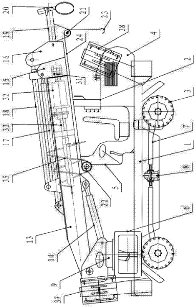
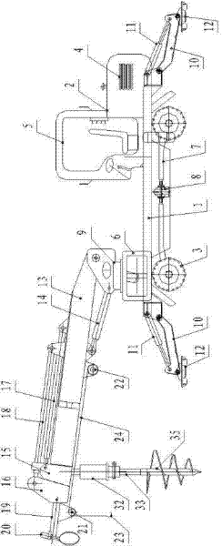
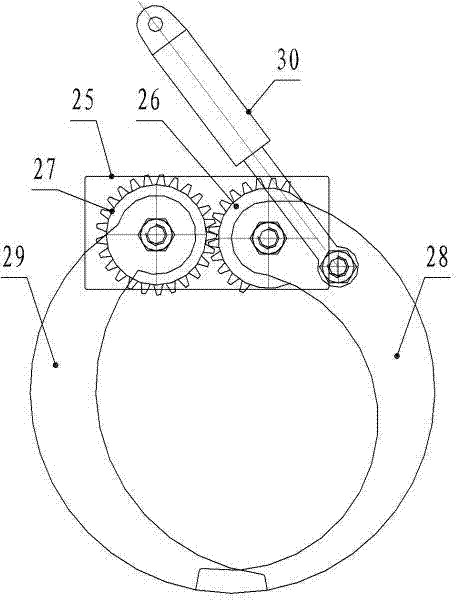
[0022] Such as Figure 1 ~ Figure 4 As shown, the multifunctional wire erecting pole machine of the present invention includes a power-operated vehicle 2 with a traveling chassis 1, a traveling wheel 3 is provided at the bottom of the traveling chassis 1, and a power mechanism 4 and a driving control room 5 are provided at the rear of the traveling chassis 1. , the front part of the walking chassis 1 is provided with a slewing bearing 6, the power mechanism 4 is connected to the driving wheels 3 through the transmission shaft 7 and the transfer case 8 located under the walking chassis 1, the power mechanism 4 is connected to the slewing bearing 6 through hydraulic transmission, and the slewing bearing 6 is connected with a rod lifting device by rotating base 9, and the bottom of the rod lifting device is provided with a drilling mechanism. Front and rear legs 37 and rear legs 38 are respectively provided with foldable front and rear legs of the walking chassis 1 . Front suppo...


PUM


Abstract

The invention discloses a multifunctional stringing pole-erecting machine which comprises a power operation vehicle with a walking chassis, wherein the lower part of the walking chassis is provided with walking wheels, the rear part of the walking chassis is provided with a power mechanism and a driving control chamber, the front part of the walking chassis is provided with a rotary support, the power mechanism is in transmission connection with the walking wheels through a transmission shaft under the walking chassis and a transfer case, the power mechanism is in hydraulic transmission connection with the rotary support, a rotary base is arranged on the rotary support, a pole lifting device is rotatably connected to the rotary base, the lower part of the pole lifting device is provided with a drilling mechanism, and the front end and the rear end of the walking chassis are respectively provided with a foldable front support leg and a foldable rear support leg. The multifunction stringing pole-erecting machine is a power grid stringing construction mechanical device integrating drilling and pole erecting, is integrally of an electrohydraulic control mode, is especially suitable for emergence rush repair when a power grid suffers from natural disasters, and is more suitable for environment with larger pole-erecting operation density in rugged and narrow places and places into which construction vehicles can not enter.

Description

technical field [0001] The invention belongs to the technical field of construction in the electric power industry, and in particular relates to a multifunctional wire erecting pole machine. Background technique [0002] In the construction of power transmission lines, erecting cement poles is an important step. In the process of erecting poles, drilling holes from the ground, erecting poles, and erecting them into the holes requires many people to complete this series of work, which requires a lot of labor. High strength, low construction efficiency and poor safety. At present, there is also a method of digging the hole first, and then using a crane to erect the pole. Because the crane is expensive and the usage fee is also high, this increases the construction cost accordingly, and the crane also needs to be equipped with a special operator, and a special person is required to use ropes to tie it up. Concrete poles have to be climbed up to remove the ropes after they are ...

Claims


Application Information

Patent Timeline
Patent Type & Authority Applications(China)
IPC IPC(8): E04H12/34
Inventor 侯东红高晓莉
Owner HENAN POWER TRANSMISSION & TRANSFORMATION CONSTR CO LTD
Learn More