Safety locks of the locking plate type especially for armored doors

A technology for locking plates and safety locks, applied in the field of safety locks or obstacles)

Active Publication Date: 2011-12-14
ISEO SERRATURE
View PDF7 Cites 4 Cited by
  • Summary
  • Abstract
  • Description
  • Claims
  • Application Information

AI Technical Summary

Problems solved by technology

[0002] As is known, one of the most important challenges for manufacturers of security locks is to counteract and disable burglary systems designed to sneak into a secured room

Method used


Image

  • Safety locks of the locking plate type especially for armored doors
  • Safety locks of the locking plate type especially for armored doors
  • Safety locks of the locking plate type especially for armored doors

Examples


Embodiment Construction

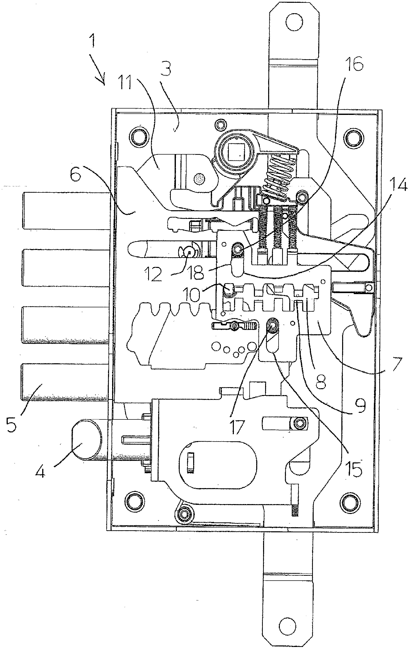
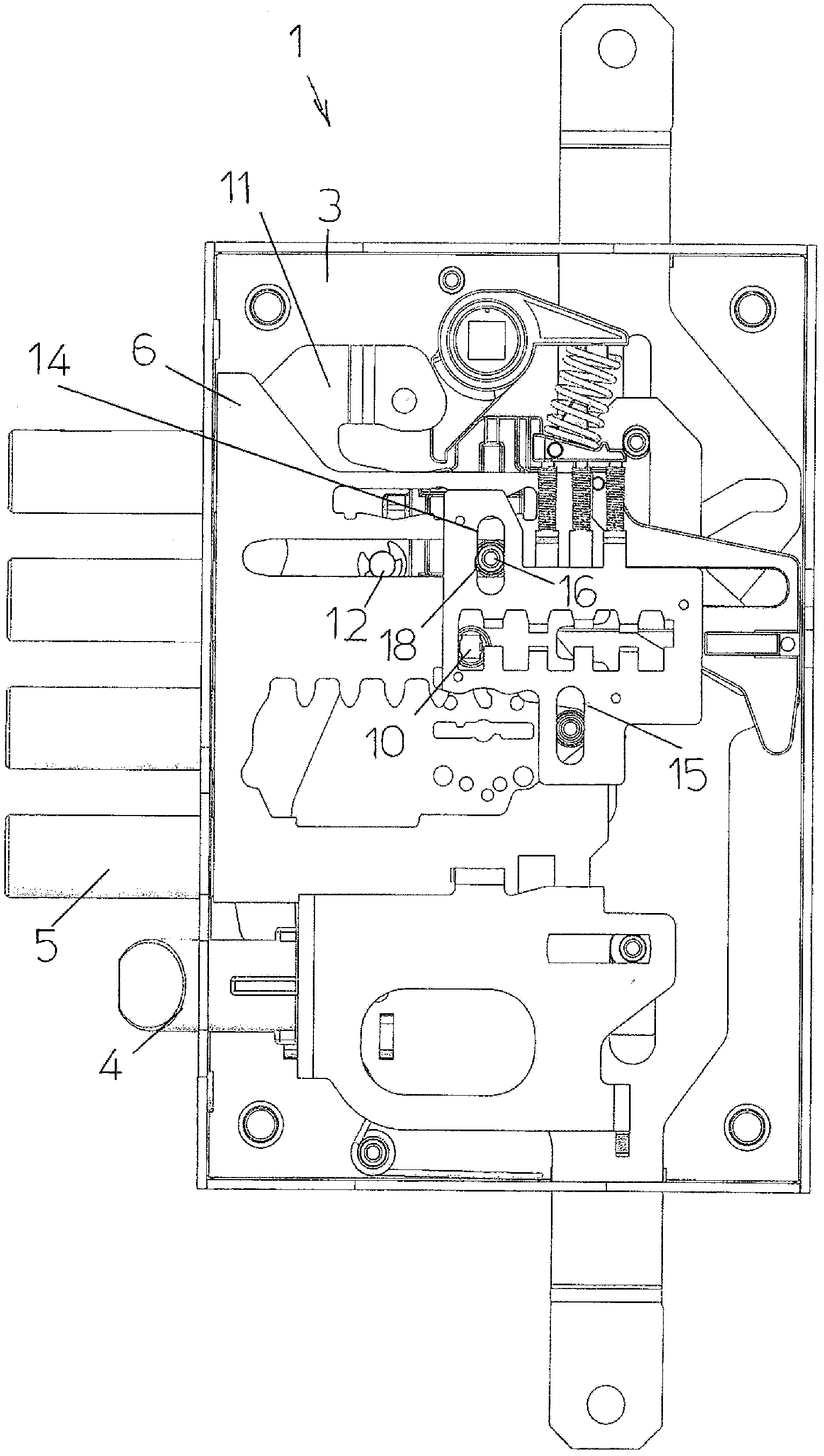
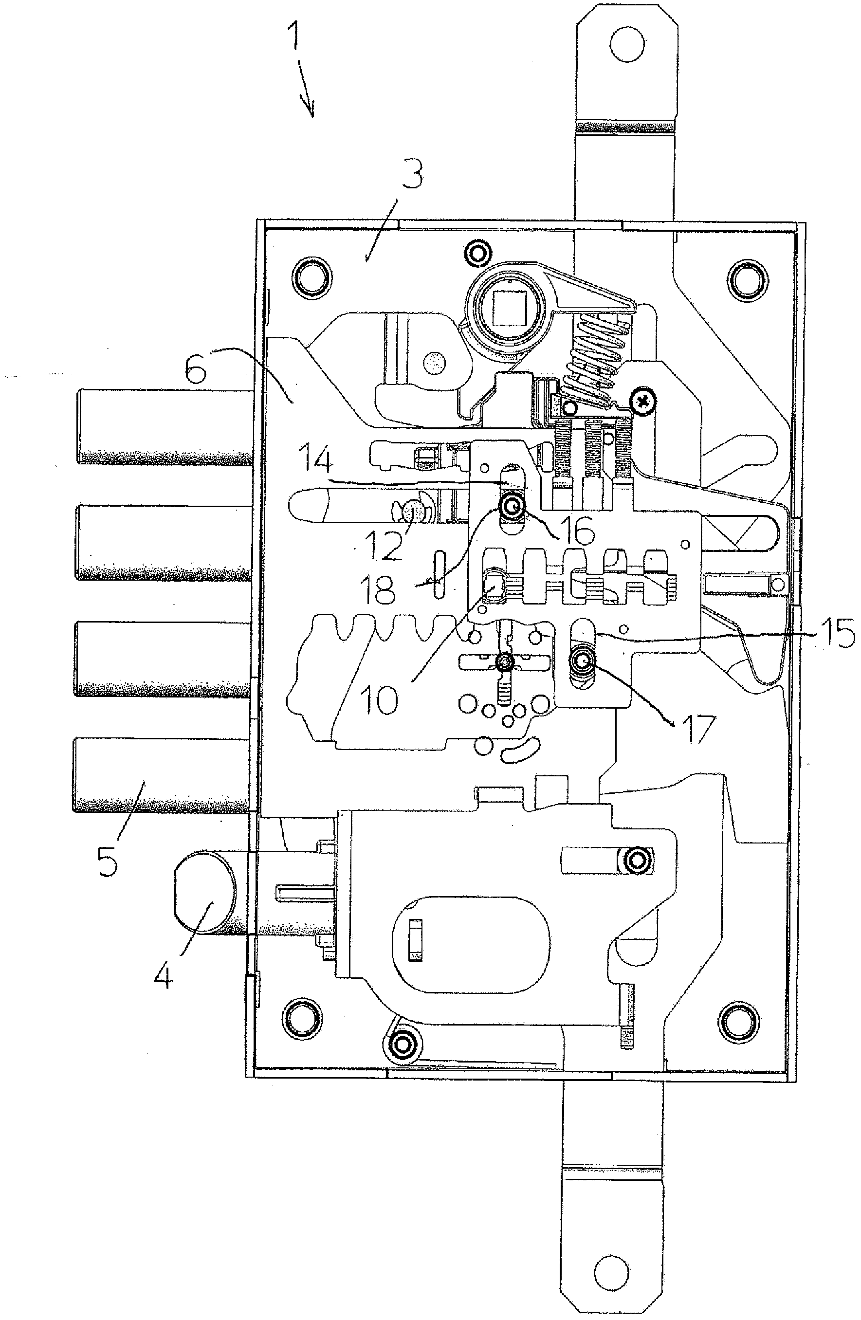
[0017] Referring to the accompanying drawings, there is shown a safety lock of the locking plate type, indicated generally by the reference numeral 1 .

[0018] The lock 1 comprises a rigid box-like housing 3 (one of the two covers has been removed for ease of illustration), inside which there is a kinematically associated bolt 4 and bolt 5 .

[0019] The cover plate of the box-like housing 3 has a hole for introducing a key with which the lock 1 can be actuated.

[0020] A bolt 5 is supported by a support plate 6 which is horizontally movable between a retracted position of the bolt 5 for opening the lock and an extended position for closing the lock 1 within the box-like housing 3 .

[0021] The latch 4 is movable horizontally in the box-like housing 3 between a retracted position for opening the lock and an extended position for closing the lock.

[0022] In order to move the bolt 4 there is an operating lever 11 for pushing the bolt 4 , which is pivoted in 12 to the box-...


PUM


Abstract

FIELD: construction.SUBSTANCE: safety lock (1) with locking plates (7), in particular, for armoured doors, comprises a system against break-in, including moving facilities, which may automatically move at least one locking plate (7) into the position of maximum lift, when at least one locking plate (7) is exposed to a blocking force in direction of crossbar (5) retraction.EFFECT: improved design.6 cl, 3 dwg

Description

technical field [0001] The present invention relates to security locks (also called levers or gorges in jargon) of the locking plate type generally used for doors, gates, safes and the like. Background technique [0002] As is known, one of the most important challenges for manufacturers of security locks is to counteract and disable burglary systems designed to sneak into a secured room. [0003] There is a specific burglary system for locking plate type security locks that uses a special tool: While a force is applied to the locking plate against the extension direction of the bolt to keep the locking plate interlocked, the locking plate is manipulated until it is broken. password. Contents of the invention [0004] The task set forth by the present invention is to provide a safety lock of the locking plate type with an extremely effective anti-theft system. [0005] In particular, with regard to this task, an important purpose of the present invention is to obtain a s...

Claims


Application Information

Patent Timeline
Patent Type & Authority Applications(China)
IPC IPC(8): E05B17/20E05B63/14
CPCE05B59/00E05B15/108E05B21/00
Inventor 费代里科·费尼尼
Owner ISEO SERRATURE
Why Eureka
Try Eureka