
An electric cabinet door control device

A kind of electrical cabinet and door control technology, which is applied in the direction of cabinet/cabinet/drawer parts, contact operating parts, etc., which can solve the problems of poor safety, insufficient light in electrical cabinets, affecting the life of lighting lamps, etc.

Inactive Publication Date: 2011-12-07
SUZHOU SUZHU IND CONTROL ENG TECH RES CENT CO LTD
View PDF0 Cites 10 Cited by
  • Summary
  • Abstract
  • Description
  • Claims
  • Application Information

AI Technical Summary

Problems solved by technology

[0002] The existing electrical cabinet products are all made of welded metal plates outside the metal frame, so the interior is relatively closed, and the light transmission and air permeability are not very good. Due to the lack of light inside the electrical cabinet, in order to ensure In the case of insufficient ambient lighting, for normal operation and maintenance of internal components, lighting lamps are generally installed in the electrical cabinet. Since the outside of the electrical cabinet is not suitable for installing the switch of the lighting lamp, the position and location of the switch installed inside the electrical cabinet Safety needs to be considered more; but if you only find the switch after opening the cabinet door, it will be very inconvenient, and the safety is not very good; if you keep the lighting on all the time, it will affect the lighting. life, and also waste power resources

Method used


Image

  • An electric cabinet door control device
  • An electric cabinet door control device

Examples


Embodiment Construction

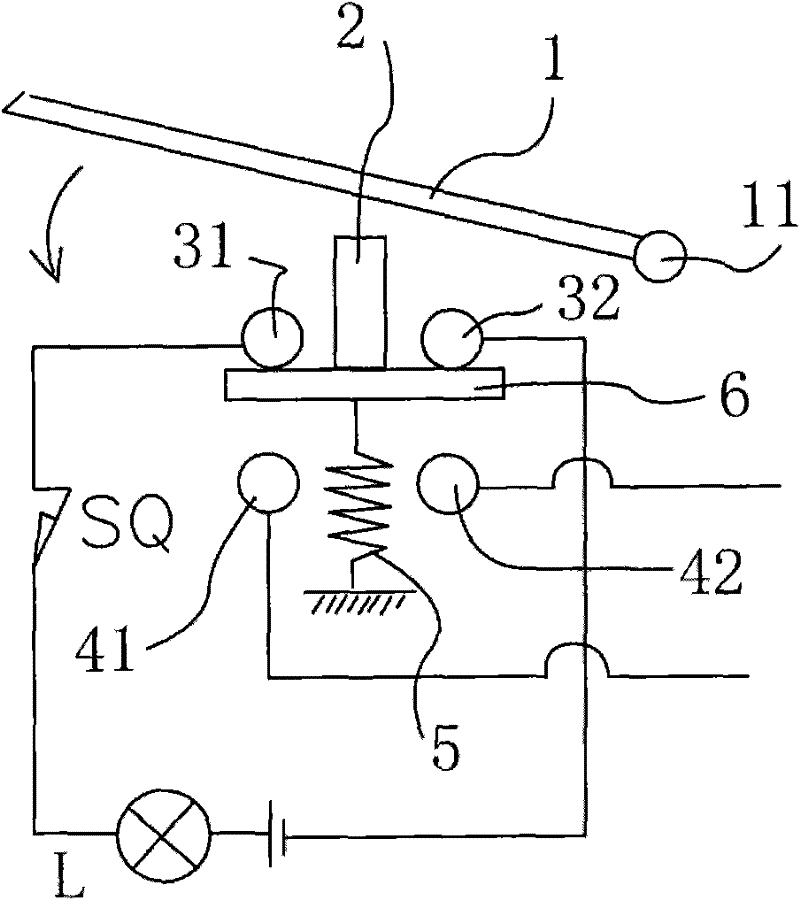
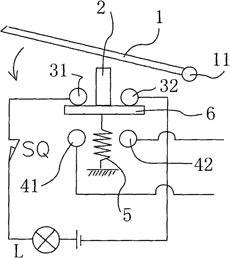
[0012] Such as figure 1 The structure and usage diagram of the door control device of the electric cabinet are shown, the normally closed contact SQ is connected in series with the lighting lamp L, and is connected with a power supply, and the contacts 31 and 32 in the circuit are connected through the connection of the metal contact piece 6. Through, wherein the metal contact piece 6 abuts against the contacts 31 and 32 under the elastic force of the spring 5 . This state is the state when the cabinet door 1 of the electrical cabinet is opened and closed, and the lighting lamp is in the working state under this state.

[0013] When the cabinet door 1 of the electrical cabinet rotates along the rotating shaft 11 and closes in the direction of the arrow in the figure, when the cabinet door 1 is closed to a certain position, it will lean against the contact button 2 and the metal contact piece 6 connected with the contact button 2 will be connected to the contact 31 Push away w...


PUM


Abstract

The invention relates to a door control device for an electrical cabinet, comprising a contact button, one end of the contact button abuts on the door of the electrical cabinet, and the other end is connected to a metal contact piece supported by a return spring. , both ends of the metal contact piece are connected to a circuit connected in series with an electrical cabinet lighting lamp and a normally closed contact; when the return spring is tightened, the two ends of the metal contact piece are far away from the connection contacts of the circuit. The door control device realizes the purpose of automatically connecting the lighting circuit when the cabinet door is opened and automatically cutting off the lighting circuit when the cabinet door is closed through a spring-controlled door control button, which is energy-saving and safe to use.

Description

technical field [0001] The invention relates to a control device for electrical equipment, in particular to a door control device for an electric cabinet. Background technique [0002] The existing electrical cabinet products are all made of welded metal plates outside the metal frame, so the interior is relatively closed, and the light transmission and air permeability are not very good. Due to the lack of light inside the electrical cabinet, in order to ensure In the case of insufficient ambient lighting, for normal operation and maintenance of internal components, lighting lamps are generally installed in the electrical cabinet. Since the outside of the electrical cabinet is not suitable for installing the switch of the lighting lamp, the position and location of the switch installed inside the electrical cabinet Safety needs to be considered more; but if you only find the switch after opening the cabinet door, it will be very inconvenient, and the safety is not very good...

Claims


Application Information

Patent Timeline
Patent Type & Authority Applications(China)
IPC IPC(8): H05K5/02H01H3/16
Inventor 钱洪海
Owner SUZHOU SUZHU IND CONTROL ENG TECH RES CENT CO LTD
Learn More