Fin for heat exchanger and heat exchanger with fin
A technology of heat exchangers and fins, applied in the field of heat exchangers, can solve the problems of no help in heat exchange, reduction of effective air volume, loss of air volume, etc., and achieve the effect of reducing the gap area, uniform wind field, and exerting heat transfer capacity
- Summary
- Abstract
- Description
- Claims
- Application Information
AI Technical Summary
Problems solved by technology
Method used
Image

Examples
Embodiment 1
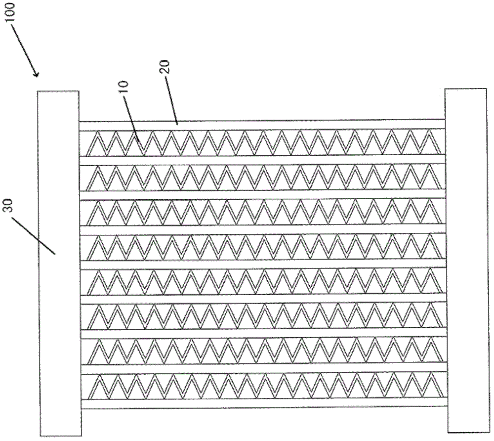
[0036] refer to figure 1 , the heat exchanger 100 such as a microchannel heat exchanger includes: tubes 20 such as flat tubes, fins 10 arranged alternately with the tubes 20 , and headers 30 arranged at both ends of the tubes 20 .
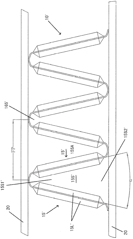
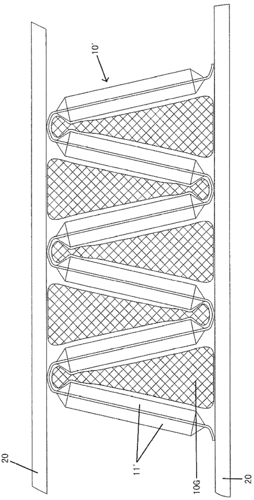
[0037] Such as Figure 4-6 As shown, the fins 10 may be generally triangular corrugated fins. The fin 10 includes a fenestrated portion 15, which may be a generally flat plate-shaped portion. A substantially tapered space 15S is formed between adjacent fenestration portions 15, and the substantially tapered space 15S has a first end portion 15S1 and a second end portion 15S2, the width of the first end portion 15S1 being smaller than that of the second end portion. 15S2 width. refer to figure 2 as well as Figure 4 , the width is measured in the same direction as the fin pitch FP. The fin 10 also includes a curved section 16 connected between adjacent window openings 15 , such as a curved plate section. After installation, at least a portio...
Embodiment 2
[0043] Figure 7 and Figure 8 The structure of the fin according to the second embodiment of the present invention is shown. The difference between the second embodiment and the first embodiment is that a third window opening is added on the basis of the first embodiment. Only the structure different from the first embodiment will be described below.
[0044] Such as Figure 7 and 8 As shown, the fin 10 further includes a third fenestration 15L3 located between the first fenestration 15L1 and the second fenestration 15L2 of the fenestration 15 . That is, the third fenestration 15L3 is located between the first fenestration 15L1 and the second fenestration 15L2 in the lateral direction LD of the fenestration portion. The window opening width LW1 of the third window opening 15L3 extending into the approximately tapered space 15S is the same as the opening width LW1 of the first window opening 15L1 extending into the approximately tapered space 15S. 15L2 protrudes between ...
Embodiment 3
[0048] Figures 9 to 14 A fin according to a third embodiment of the invention is shown.
[0049] Such as Figure 9-14 As shown, the fin 10 includes fenestrations 15 and curved sections 16 connected between adjacent fenestrations 15 . The fin 10 also includes a protruding portion 16P extending from the curved section 16 generally toward the generally conical space 15S. That is, the protruding portion 16P protrudes from the inner surface of the curved section 16 toward the space 15S. The protruding portion 16P may have any suitable shape, for example, the protruding portion 16P has a substantially circular cross-section, such as Figure 9 and 11 as shown, or roughly triangular, as in Figure 12 and 14 shown. The section is parallel to the direction of the fin pitch FP (see figure 2 ) and fin height H direction.
[0050] A plurality of protruding parts 16P can be arranged at certain intervals on the entire length L of the curved section 16, and the protruding parts 16P...
PUM
 Abstract
Description
Claims
Application Information
 - R&D
- Intellectual Property
- Life Sciences
- Materials
- Tech Scout
- Unparalleled Data Quality
- Higher Quality Content
- 60% Fewer Hallucinations
Browse by: Latest US Patents, China's latest patents, Technical Efficacy Thesaurus, Application Domain, Technology Topic, Popular Technical Reports.
© 2025 PatSnap. All rights reserved.Legal|Privacy policy|Modern Slavery Act Transparency Statement|Sitemap|About US| Contact US: help@patsnap.com