Workpiece holding method

A workpiece and process technology, applied in the direction of manufacturing tools, instruments, manipulators, etc., can solve the problems of falling off the target workpiece and being unable to hold the target workpiece, and achieve the effect of improving the success rate of holding

Inactive Publication Date: 2011-11-09
HONDA MOTOR CO LTD
View PDF5 Cites 4 Cited by
  • Summary
  • Abstract
  • Description
  • Claims
  • Application Information

AI Technical Summary

Problems solved by technology

When holding such a bulk workpiece with a multi-fingered hand, the workpiece can be held by one set of fingers while the other set of fingers interferes with other workpieces without overlapping other workpieces on the target workpiece to be held. The target workpiece cannot be held, and as a result, there is a problem that the target workpiece falls

Method used


Image

  • Workpiece holding method
  • Workpiece holding method
  • Workpiece holding method

Examples


Embodiment Construction

[0025] Hereinafter, an embodiment of the present invention will be described based on the drawings.

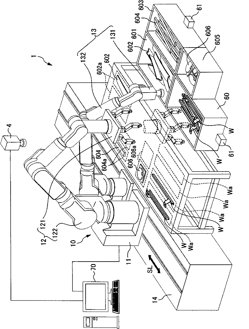
[0026] figure 1 It is a figure which shows the schematic structure of the workpiece placement system 1 which is a workpiece|work placement system used for the gripping method of the workpiece|work which concerns on one Embodiment of this invention.

[0027] The workpiece dispensing system 1 is installed on an auxiliary line that supplies a predetermined number of workpieces (assembled parts) to an assembly line for assembling automobiles in a state (equipped state) in which a predetermined number of workpieces (assembly parts) are arranged in advance at predetermined positions of a workpiece supply mechanism. Supply workpieces. The steel bar W as a workpiece in a state accommodated in the hopper 60 is supplied to the workpiece allocation system 1 . Also, the workpiece 602 accommodated in the hopper 601 , the workpiece 604 accommodated in the hopper 603 , and the workpiece 60...


PUM


Abstract

It is an object of the present invention to provide a workpiece holding method which enables a workpiece to be held when a multi-fingered hand is used to grasp the workpiece that is in an untidy heap, even if a target workpiece is subject to interference from another workpiece, and thereby the method enhances the success rate for holding the workpiece. A workpiece holding method, when two holding devices (first to fourth fingers F1 to F4) are used to hold a workpiece (reinforcement W), including a unilateral holding process of inserting a first holding device (the first finger F1 and the second finger F2) at one holding device insert position (region A) to hold and lift a workpiece-to-be-held (reinforcement-to-be-held T) in a state where the workpiece-to-be-held has no interference from any other workpieces at the region A, and a bilateral holding process of inserting a second holding device (the third finger F3 and the fourth finger F4) around (region D) the workpiece-to-be-held lifted by the first holding device, to hold the workpiece-to-be-held.

Description

technical field [0001] The present invention relates to a method of holding a workpiece, and more particularly to a method of holding a plurality of workpieces in a bulk state using two holding devices. Background technique [0002] Conventionally, mechanical products such as automobiles are manufactured by combining multiple parts. Specifically, for example, a plurality of robots are arranged in a production line to transport vehicle bodies and the like along the production line, and the workpieces (assembled parts) to be mounted on the vehicles are stored in box-shaped hoppers (trays), and the hoppers are placed on the supply for each robot. Each robot uses the fingers of the hand provided at its front end to hold the workpiece in the hopper and install it with respect to the automobile body conveyed in the production line, or to hold each workpiece in a plurality of hoppers, and make it relative to the next machine. In preparation for the assembly process of the motor v...

Claims


Application Information

Patent Timeline
Patent Type & Authority Applications(China)
IPC IPC(8): B25J15/10B25J15/00
CPCG05B2219/39485G05B2219/40604G05B2219/39114G05B2219/39503B25J9/0084B25J15/0009B25J9/1612B25J9/1697G05B2219/40053Y10T29/49998B25J9/1679B25J13/08B25J15/10
Inventor 近藤俊之泽田信治难波伸宏
Owner HONDA MOTOR CO LTD
Why Eureka
Try Eureka