Position pointer, variable capacitor and inputting apparatus
一种指示器、电容器的技术,应用在改变电极间距离的电容器、采用电/磁装置传递传感构件、数据处理的输入/输出过程等方向,能够解决可变电容器耐久性下降等问题,达到削减制造工时、提高耐久性的效果
- Summary
- Abstract
- Description
- Claims
- Application Information
AI Technical Summary
Problems solved by technology
Method used
Image
Examples
no. 1 Embodiment approach
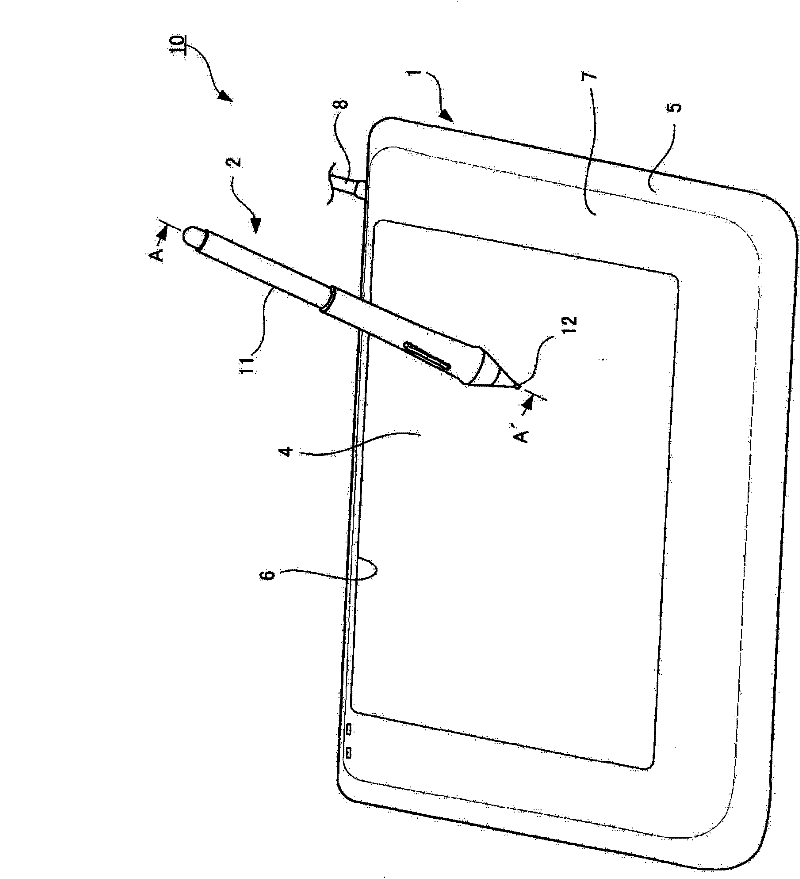
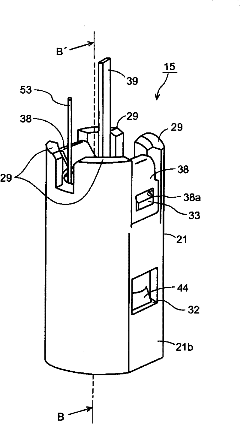
[0063] refer to Figure 1 to Figure 25 A first embodiment of the position indicator, variable capacitor, and input device of the present invention will be described. However, the same reference numerals are assigned to the same components in each figure. And the present invention is not limited to the following embodiments.
[0064] [input device]
[0065] first according to figure 1 A schematic configuration of an embodiment of the input device of the present invention will be described. Should figure 1 It is a perspective view showing an embodiment of the input device of the present invention.
[0066] The input device 10 according to the first embodiment of the present invention is composed of a position detection device 1 and a position indicator 2 for inputting information to the position detection device 1 .
[0067] [Position detection device 1]
[0068] The position detection device 1 is connected to an external device not shown in the figure, such as a person...
no. 2 Embodiment approach
[0202] The difference between the second embodiment and the first embodiment is the structure of the contact portion between the flat portion 37 of the terminal member 23 and the first surface portion 22a of the dielectric in the variable capacitor of the position indicator. Figure 26 It is a figure which shows the structure of the variable capacitor 150 of a position indicator in this 2nd Embodiment. in the Figure 26 The same reference numerals are assigned to the same parts of the variable capacitor 150 as those of the variable capacitor 15 in the above-mentioned first embodiment to omit detailed description.
[0203] In this second embodiment, the flat portion 37 of the terminal member 23 provided on the first surface portion 22a side of the dielectric 22 is not in direct contact with the first surface portion of the dielectric 22, but is formed between the flat portion 37 of the terminal member 23 and the dielectric 22. A conductive elastic member 81 made of, for exampl...
no. 3 Embodiment approach
[0208] The difference between the third embodiment and the first and second embodiments is also the structure of the contact portion between the flat portion 37 of the terminal member 23 and the first surface portion 22a of the dielectric in the variable capacitor of the position indicator. That is, in this third embodiment, as Figure 28 As shown, the electrode layer 82 is formed on the first surface portion 22a of the dielectric 22 in a region equal to or larger than the area in contact with the flat portion 37 of the terminal member 23 . The electrode layer 82 is formed by, for example, firing a silver paste on the first surface portion 22 a of the dielectric 22 . Other structures are the same as those of the first embodiment described above.
[0209] With such a structure, in the variable capacitor according to the third embodiment, the flat portion 37 of the terminal member 23 receives the pressing force due to the elastic force of the terminal member 23, and reliably to...
PUM
 Abstract
Description
Claims
Application Information
 - Generate Ideas
- Intellectual Property
- Life Sciences
- Materials
- Tech Scout
- Unparalleled Data Quality
- Higher Quality Content
- 60% Fewer Hallucinations
Browse by: Latest US Patents, China's latest patents, Technical Efficacy Thesaurus, Application Domain, Technology Topic, Popular Technical Reports.
© 2025 PatSnap. All rights reserved.Legal|Privacy policy|Modern Slavery Act Transparency Statement|Sitemap|About US| Contact US: help@patsnap.com


