Ice maker, hollow mold therefor and ice piece made therewith

An ice machine, hollow technology, applied in the field of refrigeration appliances and ice cubes, can solve the problems of energy consumption, affecting the total efficiency of refrigeration appliances, etc., and achieve the effect of easy removal

Inactive Publication Date: 2011-09-14
BSH BOSCH & SIEMENS HAUSGERAETE GMBH
View PDF7 Cites 0 Cited by
  • Summary
  • Abstract
  • Description
  • Claims
  • Application Information

AI Technical Summary

Problems solved by technology

Also, the shallow thawing of ice cubes requires significant energy consumption, which negatively affects the overall efficiency of the refrigeration appliance in which this ice maker is installed

Method used


Image

  • Ice maker, hollow mold therefor and ice piece made therewith
  • Ice maker, hollow mold therefor and ice piece made therewith
  • Ice maker, hollow mold therefor and ice piece made therewith

Examples


Embodiment Construction

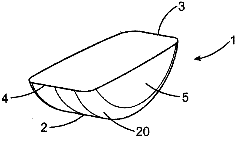
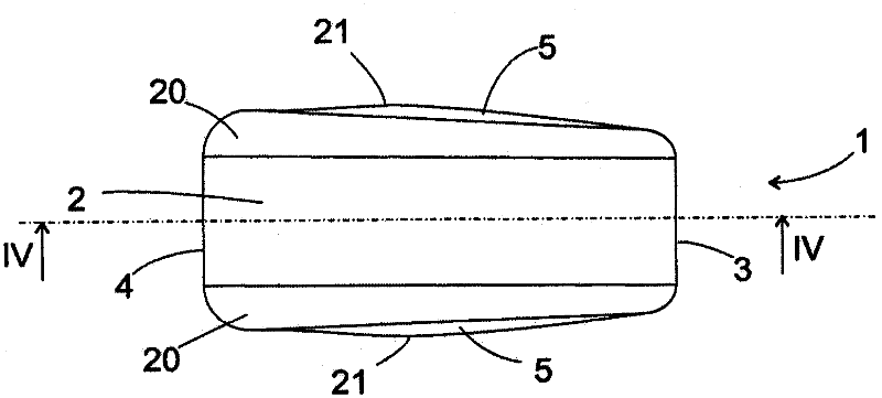
[0022] figure 1 A perspective view of the ice cube 1 of the present invention is shown. The shape of the ice cube 1 is similar to a segment of a cylinder, where the cylinder has a flat top side and rounded corners between the side and end faces of the cylinder, but the cylinder is in the shape of a perfect cylinder. There are deviations in some characteristics. On the one hand, the curved side surface 2 of the ice cube 1 corresponding to the cylindrical sleeve is not exactly cylindrical, but has the shape of an Archimedes spiral in cross section. The radius of curvature of the spiral is on the side surface 2 keep away figure 1 The edge 3 of the observer in the perspective view is smaller than the opposite edge 4 facing the observer. On the other hand, the width of ice cube 1 increases from edge 3 to edge 4, as especially in figure 2 The illustrated view of the ice cube 1 is clearly visible from below, and the end side surface 5 of the ice cube 1 corresponding to the end surfa...


PUM


Abstract

A hollow mold (7) for preparing ice pieces (1), in particular in an automatic ice maker, has an open top side and a base (8) that is continuously curved between two opposing edge points (13, 14) of the top side in an intersecting plane perpendicular to the top side. The radius of curvature of the base (8) decreases monotonically along the intersecting plane from one of the edge points (13) to the other edge point (14).

Description

Technical field [0001] The present invention relates to an automatic ice maker and particularly to a hollow mold used in such an ice maker to freeze water therein. The present invention also relates to a refrigeration appliance having such an ice maker and the use of such an ice maker or hollow mold Obtained ice cubes. Background technique [0002] From the patent publication DE 10 2005 003 241 A1, an automatic ice maker is known. In this automatic ice maker, the bracket can pivot about an axis between a filling or freezing position and a dispensing position, wherein, A plurality of hollow molds are formed in the bracket, and in the filling or freezing position, the opening of the hollow mold points upward, and in the dispensing position, the opening of the hollow mold faces downward. In order to help release the ice cubes made from the hollow mold of the tray, the tray is provided with electric heating equipment, wherein the electric heating equipment allows the ice cubes to be...

Claims


Application Information

Patent Timeline
IPC IPC(8): F25C1/24
CPCF25C1/24F25C2500/02F25C2305/022F25C2400/10F25C2500/08F25C2305/0221
Inventor B·沃尔夫B·黑格尔
Owner BSH BOSCH & SIEMENS HAUSGERAETE GMBH
Why Eureka
Try Eureka