Connector

A technology of connectors and terminal joints, applied in the field of connectors, can solve problems such as cost increase

Active Publication Date: 2011-08-17
SUMITOMO WIRING SYST LTD
View PDF5 Cites 12 Cited by
  • Summary
  • Abstract
  • Description
  • Claims
  • Application Information

AI Technical Summary

Problems solved by technology

However, if a seal is prepared, it will lead to an increase in cost, so a waterproof structure as simple as possible is desired

Method used


Image

  • Connector
  • Connector
  • Connector

Examples


Embodiment Construction

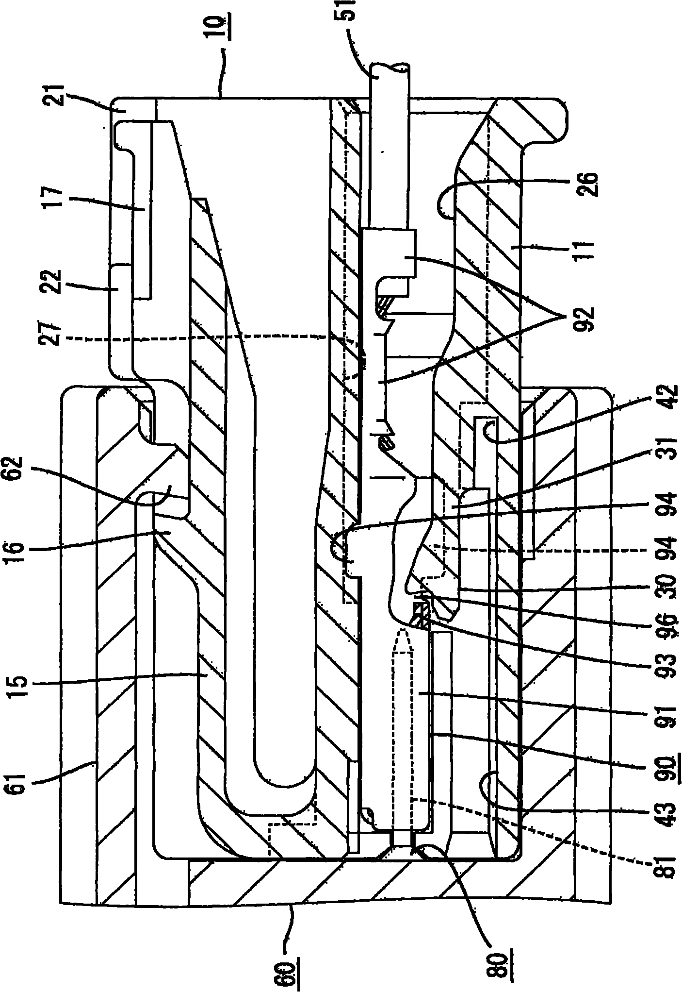
[0043] refer to Figures 1 to 9 A preferred embodiment of the present invention is described. The connector according to this embodiment is smaller than usual connectors, includes a housing 10 and one or more terminal fittings 90, and can be connected with a mating housing. Regarding the front-rear direction, in the following description, the side to be connected of the two casings 10, 60 is referred to as the front side.

[0044] The mating connector includes a mating housing 60 made of synthetic resin, for example. Such as figure 1 As shown, the mating housing 60 comprises a receptacle 61 (in particular substantially in the form of a rectangular tube) into which one or more corresponding tabs 81 of one or more male terminal fittings 80 are arranged to protrude at least partially. The locking portion 62 is formed to protrude from (specifically, the inner surface of the upper wall of) the receptacle 61 .

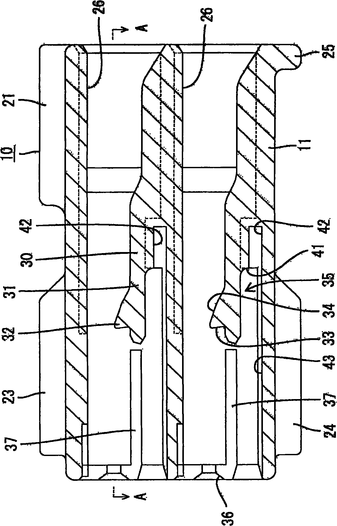
[0045] The housing 10 is made of, for example, synthetic resin, and...


PUM


Abstract

A waterproof connector has a deformation space (35) for a locking lance (30) that opens in the front surface of a housing (10). A wall surface (41) of a base end part of the locking lance (30) is located at a back side of the deformation space (35). In the process of inserting a terminal fitting (90) into a cavity (26), the locking lance (30) is resiliently deformed toward the deformation space (35) with a base end thereof as a support. When the terminal fitting (90) is inserted properly into the cavity (26), the locking lance (30) resiliently returns to retain the terminal fitting (90) in the cavity (26). A recess (42) is formed in the wall surface (41) of the base end portion of the locking lance (30).

Description

technical field [0001] The invention relates to a connector. Background technique [0002] Japanese Unexamined Patent Publication No. 2009-231077 discloses a conventional connector. The connector includes a housing formed with a cavity, and locking lances that are elastically deformable and protrude forward are formed on an inner surface of the cavity in the housing. The deformation space for the locking lance is opened on the front surface of the housing, and the wall surface of the base end portion of the locking lance is located on the rear side of the deformation space. [0003] Insert the terminal fitting into the cavity of the housing from the rear. During insertion, the terminal fitting interferes with the locking lance, and the locking lance elastically deforms toward the deformation space with its end as a fulcrum. Thereafter, when the terminal fitting is correctly inserted, the locking lance elastically returns to lock the terminal fitting. [0004] The convent...

Claims


Application Information

Patent Timeline
Patent Type & Authority Applications(China)
IPC IPC(8): H01R13/40H01R13/52
CPCH01R13/4223
Inventor 千种贵弘
Owner SUMITOMO WIRING SYST LTD
Why Eureka
Try Eureka