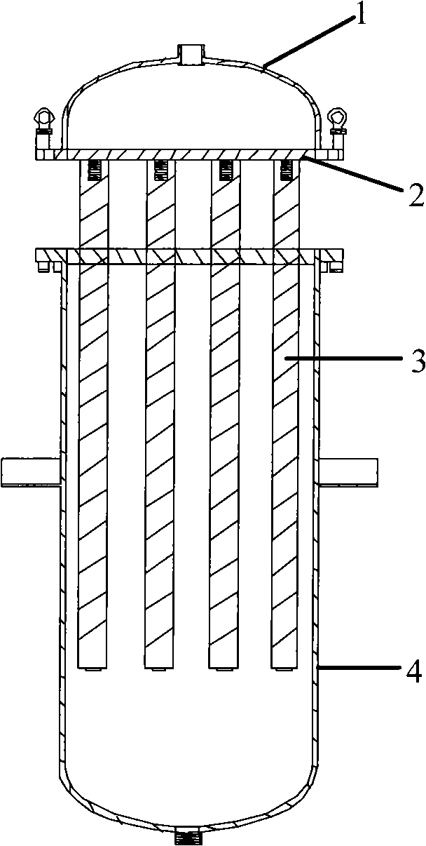
Filter vat
A filter barrel and filter element technology, applied in the field of filter barrels, can solve the problems of time-consuming and laborious disassembly, cumbersome installation, and unclean filtration.
Inactive Publication Date: 2011-06-15
SUZHOU YONGTIAN TECH EQUIP +1
View PDF5 Cites 2 Cited by
- Summary
- Abstract
- Description
- Claims
- Application Information
AI Technical Summary
Problems solved by technology
The disadvantages are: 1) The screws on the barrel cover and the nuts of the filter element on the flange must be disassembled one by one, which takes time and effort to disassemble, and requires special tools; Because it is not fixed, the filter element will move when the nut on the filter element is tightened, so two people must work together; 3) Each filter element must be equipped with an O-ring to avoid oil leakage. If it is not installed properly, it will easily leak oil and the filter will not be clean; 4) An O-ring must be installed between the barrel body, flange, and barrel cover to prevent leakage, and there is an additional risk of oil leakage; the filter element is designed with paper, and the filter rod Made of steel, the paper will absorb oil and tungsten mud, so it is very heavy, so it must be lifted with a hoist or a crane
The structure of the filter barrel is relatively heavy, and the installation is very cumbersome. It is very difficult to assemble, maintain and replace the filter element in the future. It requires special spreaders, special tools and at least two professional technicians to replace and assemble. The maintenance cost is very high. Manufacturers and users will have a great burden
Method used
View moreImage
Smart ImageViewing Examples
Examples
Embodiment Construction
Login to View More PUM
 Abstract
The invention provides a filter vat comprising a vat cover, a vat body and filter elements, wherein the bottom surface of the vat cover is in welded connection with the upper plane of a flange; a plurality of screws are vertically welded on the lower plane of the flange; internal threads matched with the screws on the flange are formed on the upper ends of the filter elements; the filter elements are in threaded connection with the flange; the filter elements are arranged in an inner cavity of the vat body; and the flange is fixedly connected with the vat body. In the invention, the vat cover and the flange are connected into a whole and are separated from the vat body into two main bodies, and because the plurality of screws are welded on the flange, the filter elements can be disassembled one by one quickly and easily without using special tools.
Description
filter bucket technical field The invention relates to an oil (water) filter device, in particular to a filter bucket. Background technique At present, the barrel cover, the flange plate and the barrel body of the filter barrel are three separate main bodies. During maintenance, it is necessary to use a hoist to remove the screws on the barrel cover, take out the barrel cover, and then lift the flange plate to fix it on the Remove the nuts on the filter element on the flange one by one, and then take out the filter element. The disadvantages are: 1) The screws on the barrel cover and the nuts of the filter element on the flange must be disassembled one by one, which takes time and effort to disassemble, and requires special tools; Because it is not fixed, the filter element will move when the nut on the filter element is tightened, so two people must work together; 3) Each filter element must be equipped with an O-ring to avoid oil leakage. If it is not installed properl...
Claims
Login to View More Application Information
Patent Timeline
 IPC IPC(8): B01D35/30
Inventor 郑添全
Owner SUZHOU YONGTIAN TECH EQUIP
Features
- R&D
- Intellectual Property
- Life Sciences
- Materials
- Tech Scout
- Unparalleled Data Quality
- Higher Quality Content
- 60% Fewer Hallucinations
Learn More Browse by: Latest US Patents, China's latest patents, Technical Efficacy Thesaurus, Application Domain, Technology Topic, Popular Technical Reports.
© 2025 PatSnap. All rights reserved.Legal|Privacy policy|Modern Slavery Act Transparency Statement|Sitemap|About US| Contact US: help@patsnap.com


