
Knee bandage

A knee bandage and bandage technology, applied in the field of knee bandages, can solve the problems of adaptive shortening of support belts and cartilage damage.

Active Publication Date: 2011-05-25
麦迪有限及两合公司
View PDF6 Cites 9 Cited by
  • Summary
  • Abstract
  • Description
  • Claims
  • Application Information

AI Technical Summary

Problems solved by technology

Likewise, adaptive shortening of the lateral retinaculum or incorrect loading of the retinaculum leads to an increased risk of damage to the retropatellar cartilage

Method used


Image

  • Knee bandage
  • Knee bandage
  • Knee bandage

Examples


Embodiment Construction

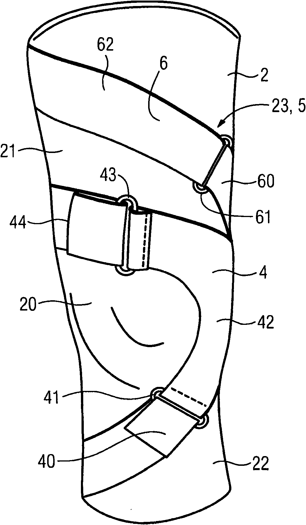
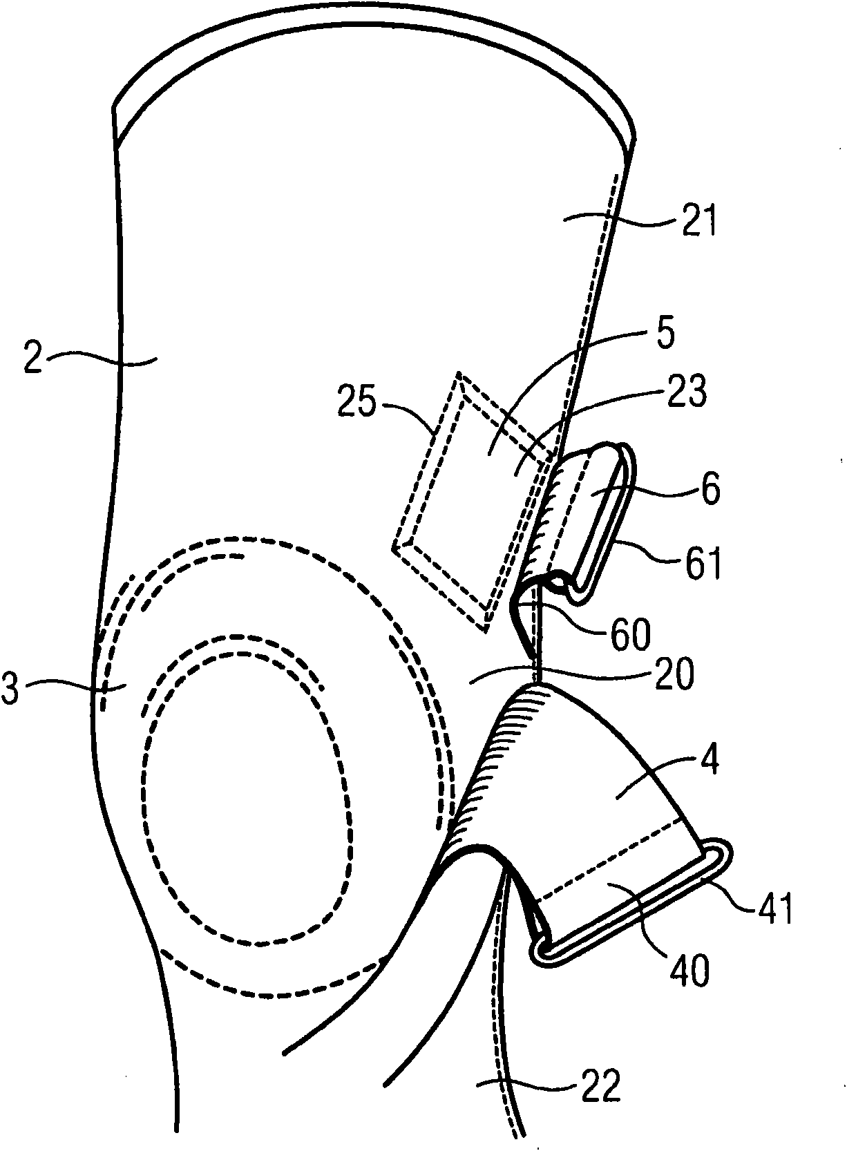
[0026] according to figure 1 and figure 2 The knee bandage comprises a flexible or tubular bandage base part 2, which is usually made of an elastic material, especially a textile, fabric or knit or braid. Suitable materials, without limiting generality, are textile materials based on synthetic fibers or cotton.

[0027] In the worn state, the dressing base part 2 completely surrounds the relevant knee and the adjoining calf and part of the thigh. The medial patella area surrounding the knee joint itself, popliteal fossa and patella is indicated at 20, the thigh area adjacent to the thigh is indicated at 21, and the calf area adjacent to the calf is indicated at 22.

[0028] In the kneecap region 20, an annular edge piece (or annular pad) 3 is fastened to the base bandage 2, which surrounds the kneecap or patella (not shown) and is especially elastic and / or cushioned. Capable materials, for example silicon elastomers (polysiloxane-based elastomers) or other elastomers. On...


PUM


Abstract

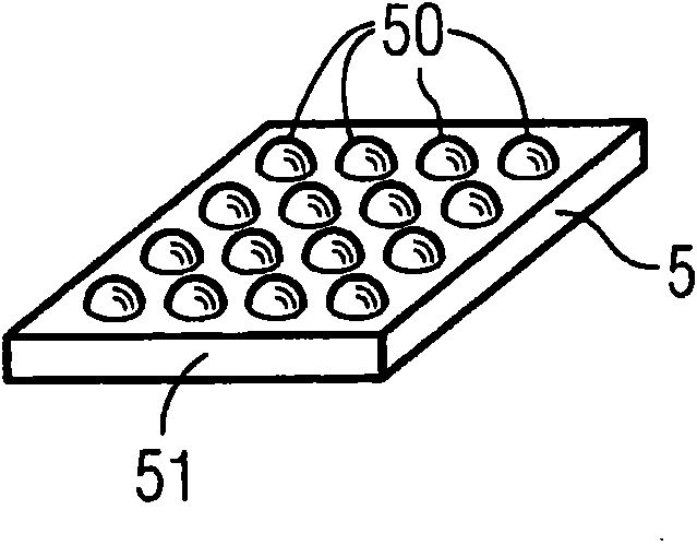
The invention relates to a knee bandage, comprising a) a bandage base element (2) having a central kneecap region (20) associated with the kneecap, a thigh region (21) adjoining the kneecap region (20) and being associated with a partial region of the thigh, and a lower leg region (22) adjoining the kneecap region (20) and being associated with a partial region of the lower leg; b), at least one massaging pelotte (5) attached to the bandage base element (2) in a massaging region (23) and having massaging elements (50) or massaging points and / or massaging surfaces directed toward the interior toward the leg when the knee bandage is tightened; and c) wherein the massaging region (23) is disposed in the thigh region (21) at the at least one massaging pelotte (5) and is associated with a trigger point or a trigger area of the musculus vastus lateralis, or wherein the massaging pelotte (5) brings about a massage of a trigger point or a trigger region of the musculus vastus lateralis when the knee bandage is tightened, particularly during the movement of the knee.

Description

technical field [0001] The present invention relates to a knee bandage. Background technique [0002] Various forms of knee bandages (or: knee joint bandages) are known. In a specific embodiment, the knee bandage functions to mechanically correct a dislocation of the kneecap (patella). The dislocation of the patella is corrected by applying lateral pressure to the patella from the outside with a mechanical aid such as a hoop or bandage. Such knee bandages are known, for example, from DE 10 2004 04 793 A1 or DE 38 38 576 A1 or US 6 287 269 B1. [0003] Anatomically, the guidance of the patella is passive on the one hand via the pulley and on the other hand is largely dependent on the movement of the outer thigh muscles (vastus lateralis) and the centrally directed thigh muscles (vastus medialis) Dynamic functions of different muscle forces. Extending centrally and laterally towards the patella and patella ligaments is a ligament, the retinaculum of the patella, which is d...

Claims


Application Information

Patent Timeline
Patent Type & Authority Applications(China)
IPC IPC(8): A61F13/02
CPCA61F2005/0176A61F5/0109A61F13/061A61F13/062A61F5/30
Inventor J·赫雷斯特尔
Owner 麦迪有限及两合公司
Learn More