
Touch input system

An input system and touch technology, applied in the input/output process of data processing, instruments, electrical digital data processing, etc., can solve the problem of increasing the setting area and achieve the effect of reducing the area

Inactive Publication Date: 2011-05-18
ACER INC
View PDF0 Cites 3 Cited by
  • Summary
  • Abstract
  • Description
  • Claims
  • Application Information

AI Technical Summary

Problems solved by technology

[0005] In view of the above-mentioned problems in the prior art, the purpose of the present invention is to provide a touch input system to solve the problem that the user needs to touch the keys multiple times to adjust the parameters, and the multiple keys of the input system lead to its setting The problem of increased area

Method used


Image

  • Touch input system
  • Touch input system
  • Touch input system

Examples


Embodiment Construction

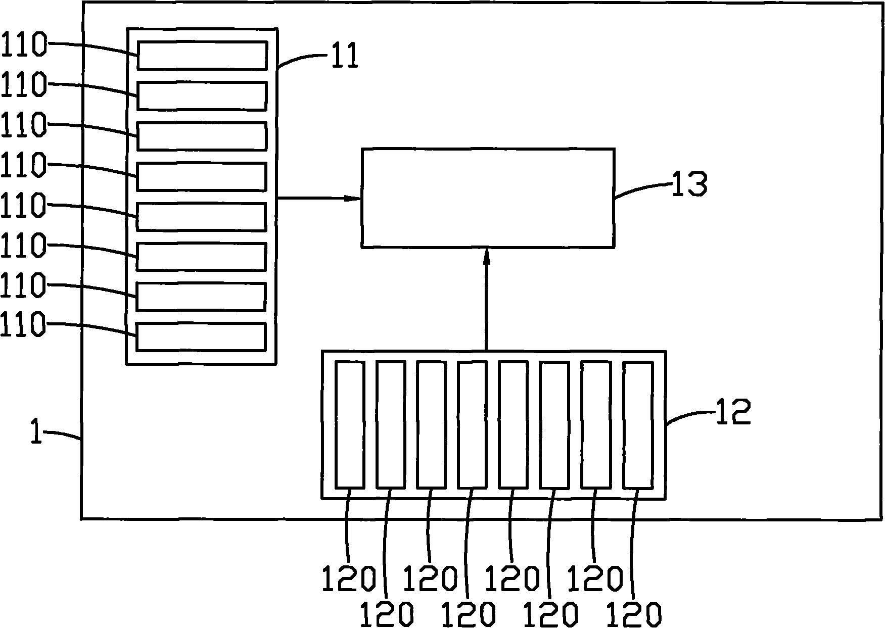
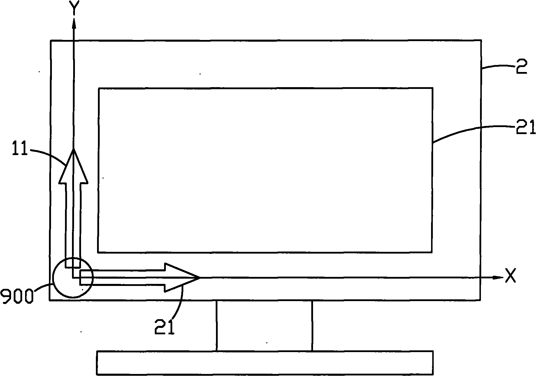
[0047] see figure 1 , which is a block diagram of the first embodiment of the touch input system of the present invention. In the figure, the touch input system 1 includes a first button module 11 , a second button module 12 and a microprocessor 13 . The first button module 11 includes a plurality of first sensing units 110 arranged on the first axis, and when at least one first sensing unit 110 is pressed, a first signal will be generated; the second button module 12 includes a set of The plurality of second sensing units 120 arranged on the second axis will generate a second signal when at least one second sensing unit 120 is pressed. The microprocessor 13 is connected to the first button module 11, the second button module 12 and the electronic device (not shown in the figure) to receive the first signal or the second signal and generate a control signal to the electronic device to correspond to the control electronics device, the electronic device is preferably a TV, a m...


PUM


Abstract

The invention discloses a touch input system used for controlling an electronic device. The touch input system comprises a first key module, a second key module and a microprocessor, wherein the first key module comprises a plurality of first sensing units arranged in a first axial direction; the second key module comprises a plurality of second sensing units arranged in a second axial direction; a first signal is generated when at least one first sensing unit is pressed down; a second signal is generated when at least one second sensing unit is pressed down; the microprocessor is connected with the first key module, the second key module and an electronic device and used for receiving the first signal and the second signal and generating a control signal so as to correspondingly control the electronic device.

Description

technical field [0001] The invention relates to a touch input system, in particular to a touch input system which simplifies input keys and increases user efficiency. Background technique [0002] At present, due to the progress of technology, the adjustable parameters of commercially available electronic devices are increasing day by day, such as TV or display screen color contrast (Contrast) or brightness (Brightness) and other options, or audio equipment to adjust the high and low pitch, radio listening frequency, etc. Considering the convenience of users, most of the parameter adjustments of these electronic devices can be set through a remote controller or an input system provided on the electronic device. [0003] The existing remote control or the input control system arranged on the electronic device has four direction keys of up, down, left and right and a confirmation key to control the electronic device. Increased area required for remote control or input control...

Claims


Application Information

Patent Timeline
IPC IPC(8): G06F3/041G06F3/044G06F3/045
Inventor 黄伟恒阎立
Owner ACER INC
Learn More