Seat sliding device

A sliding device and seat technology, applied in vehicle seats, movable seats, transportation and packaging, etc., can solve the problems of fixed center of gravity and difficulty in adjustment

Inactive Publication Date: 2013-03-20
IMASEN ELECTRIC IND
View PDF1 Cites 0 Cited by
  • Summary
  • Abstract
  • Description
  • Claims
  • Application Information

AI Technical Summary

Problems solved by technology

[0005] However, the operation lever as described above is extended so as to be in contact with the lock lever so as to press the lock lever during locking. Therefore, there is a problem that the position of the center of gravity of the tilting body is basically fixed and difficult to adjust.

Method used


Image

  • Seat sliding device
  • Seat sliding device
  • Seat sliding device

Examples


no. 1 Embodiment approach

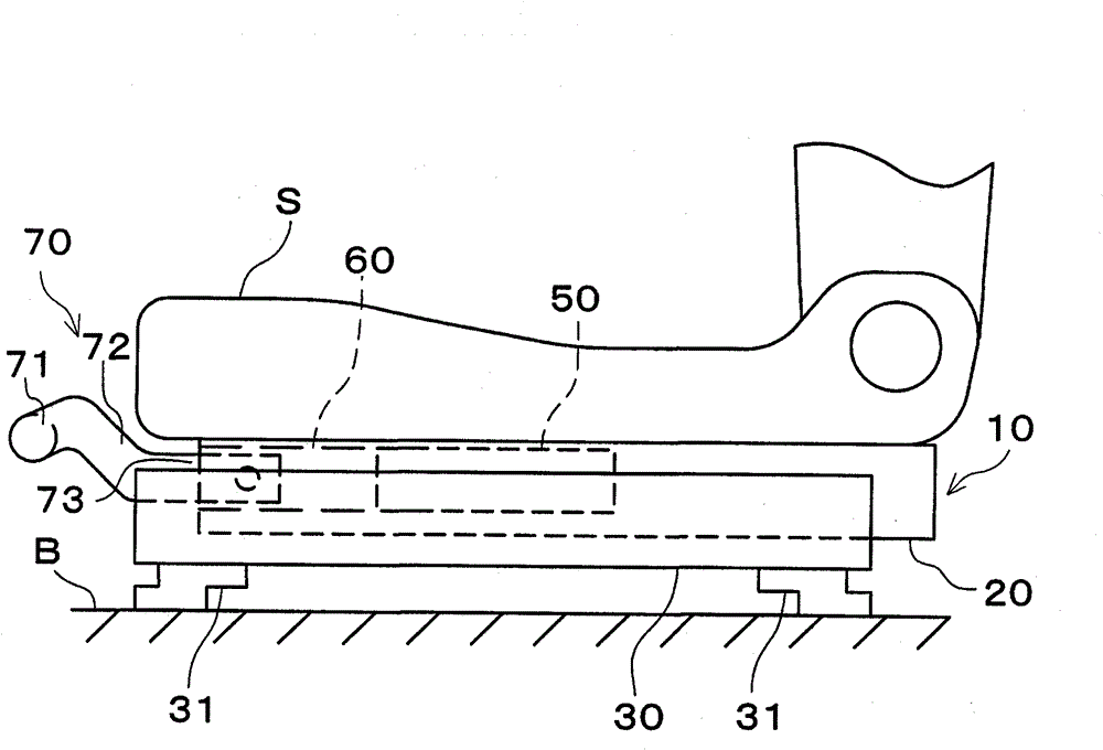
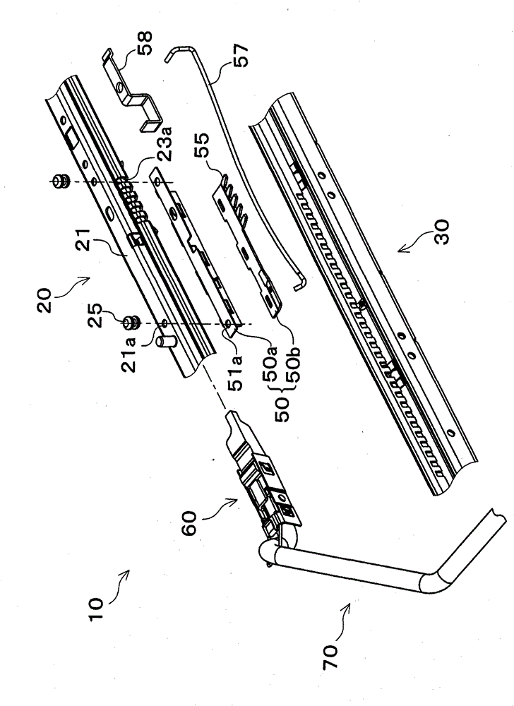
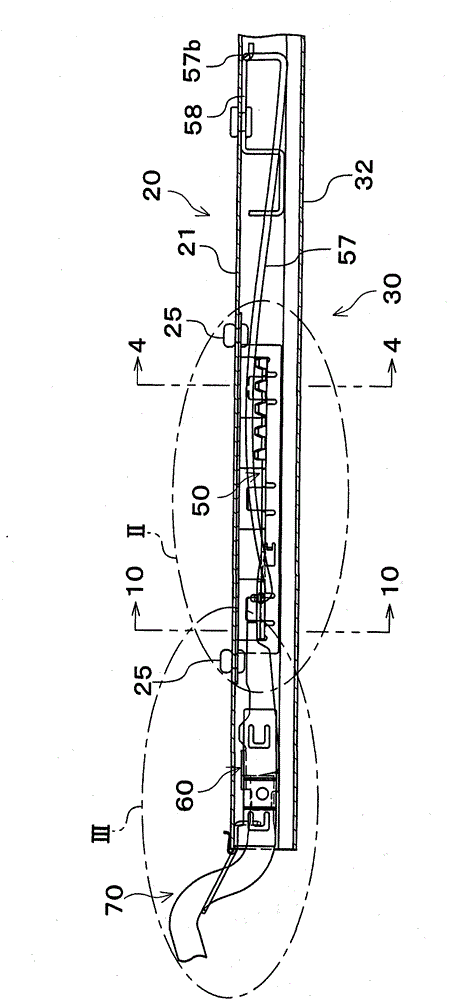
[0037] Next, a first embodiment of the present invention will be described with reference to the drawings. figure 1 It is a side view showing the schematic structure of the vehicle seat S provided with the seat sliding device 10 of the first embodiment. figure 2 yes figure 1 A partially exploded perspective view of the seat sliding device 10 in . image 3 yes figure 1 A partial sectional view of the seat sliding device 10 in . Figure 4 is along image 3 Sectional view of line 4-4 shown.

[0038] Such as Figure 1 ~ Figure 3 As shown, the seat sliding device 10 is used to fix the vehicle seat S on the vehicle floor B so that it can slide back and forth. The seat sliding device 10 mainly includes an upper guide rail 20 fixed on the vehicle seat S, and The leg portion 31 is fixed to the lower rail 30 on the vehicle floor B, the locking member 50 that can fix (lock) the upper rail 20 and the lower rail 30 so that they cannot move relative to each other, and can unlock the ...

no. 2 Embodiment approach

[0087] Next, refer to Figure 11 ~ Figure 13 A second embodiment of the present invention will be described. Figure 11 It is a perspective view which shows the main part of the seat slide apparatus 10 which concerns on 2nd Embodiment of this invention. Figure 12 yes Figure 11 An exploded perspective view of the force applying member 80 of FIG. Figure 13 (A) is a diagram showing the urging member 80 in a locked state, Figure 13 (B) is a diagram showing the urging member 80 tilted from the locked state to the anti-unlock direction. In order to illustrate the tilting state of the tilting member 83, Figure 13 (A) and (B) have shown only a part of the connection body 84 by the dashed-two dotted line, and have shown the connection body support member 81 in cross section.

[0088] The seat slide device 10 of the second embodiment differs from the seat slide device of the above-mentioned first embodiment in that an urging member is used instead of the urging member 60 and t...


PUM


Abstract

Disclosed is a seat sliding device that prevents the malfunction of operating elements. The device is provided with an energizing element (60) which energizes a locking element (50) in the rotational direction to unlock in response to operation of an operating lever (70), and which energizing element (60) can be tilted, using a shaft (62) as the tilt axis, together with said operating lever (70) in response to operation of the operating lever (70). The shape, mass, etc. of a balancer (64) on the energizing element (60) are adjusted so that the position of the center of gravity of the tilting body, which tilts with operation of the operating lever (70) and comprises the operating lever (70) and the energizing element (60), is brought close to the axis of the shaft (62).

Description

technical field [0001] The invention relates to a seat sliding device for adjusting a vehicle seat forward and backward. Background technique [0002] Conventionally, as a seat sliding device for adjusting a vehicle seat forward and backward, a vehicle seat sliding device disclosed in Patent Document 1 below is known. The lock mechanism of this vehicle seat slide device locks the upper part by fitting the claw of the lock lever fixed to the upper rail so as to be tiltable into the engaging hole of the lower rail and the engaging hole of the upper rail. The rails are locked against movement relative to the lower rails. Then, the locking is released by operating the operating lever to tilt the lock lever to pull out the claws from the engaging holes of the lower rail and the engaging holes of the upper rail. [0003] Patent Document 1: Japanese Patent Laid-Open No. 2002-154356 [0004] However, when the vehicle on which the passenger rides collides or when emergency braking...

Claims


Application Information

Patent Timeline
Patent Type & Authority Patents(China)
IPC IPC(8): B60N2/08
CPCB60N2/0881
Inventor 木村学二佐藤祐辅三好健介村井伸行
Owner IMASEN ELECTRIC IND
Why Eureka
Try Eureka