Appliance monitor

A technology for monitoring equipment and appliances, which is applied in the field of appliance monitoring equipment and can solve problems such as inability to solve social needs.

Inactive Publication Date: 2012-05-30
PANASONIC CORP
View PDF2 Cites 0 Cited by
  • Summary
  • Abstract
  • Description
  • Claims
  • Application Information

AI Technical Summary

Problems solved by technology

This appliance monitoring device does not address the social need to know the aforementioned information against the backdrop of growing concern for the global environment

Method used


Image

  • Appliance monitor
  • Appliance monitor

Examples


no. 1 example

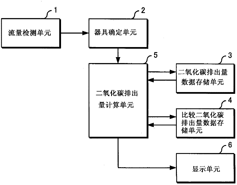
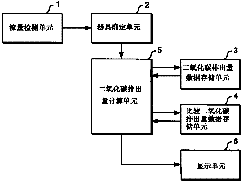
[0026] figure 1 is a control block diagram of the appliance monitoring device of the first embodiment of the present invention.

[0027] exist figure 1Inside, reference numeral 1 designates a flow detection unit arranged in a gas flow path in the gas meter. Reference numeral 2 denotes an appliance determination unit configured to determine a gas appliance used by a customer. Reference numeral 3 denotes a carbon dioxide emission data storage unit configured to store a carbon dioxide emission predetermined for each gas appliance as a database. Reference numeral 4 denotes a comparative carbon dioxide emission data storage unit configured to store in advance the carbon dioxide emission generated during combustion of an appliance to be compared with a gas appliance used by a customer as a database. Reference numeral 5 denotes a carbon dioxide emission calculating unit configured to be based on data related to the carbon dioxide emission of the gas appliance selected from the car...


PUM


Abstract

A convention appliance monitoring apparatus handles only the amount of gas used and security information for the case of a gas cutoff and can not address social needs for a desire to obtain information about influence (e.g., an amount of CO2 emission) of use of the gas combustion appliance on a terrestrial environment. Based on a gas appliance used by a client and a gas flow signal pertaining thegas appliance which are output from an appliance determination unit 2, CO2 emission data on the gas appliance stored in a CO2 emission data storage unit 3, and CO2 emission data which are to be compared with the gas appliance and stored in a comparative CO2 emission data storage unit 4, a CO2 emission calculation unit 5 calculates an amount of CO2 emission, an comparative amount of CO2 emission and a difference between the amount of CO2 emission and the comparative amount of CO2 emission. Accordingly, it is possible to determine the amount of CO2 emission produced by using the gas appliance and the difference between the amount of CO2 emission and the comparative amount of CO2 emission.

Description

technical field [0001] The present invention relates to an appliance monitoring device for calculating and determining the amount of carbon dioxide emission, etc., generated during combustion by a gas burning appliance using, for example, domestic gas, liquefied petroleum gas, or the like. Background technique [0002] Conventionally, this type of appliance monitoring apparatus monitors safety information such as the amount of gas consumed by a gas burning appliance and the reason for shutting off when the gas is turned off (see, for example, Patent Document 1). [0003] Patent Document 1: JP-A-2001-236116 Contents of the invention [0004] However, conventional appliance monitoring apparatuses only deal with the amount of gas used and safety information for the situation of gas cutoff, and do not consider the impact of the use of gas burning appliances on the global environment (for example, carbon dioxide emission). This appliance monitoring device cannot address the ne...

Claims


Application Information

Patent Timeline
Patent Type & Authority Patents(China)
IPC IPC(8): G01F3/22
CPCF23N2023/54G01F3/22F23N2900/05002Y02E20/328F23N5/184F23N5/003F23N5/24F23N2023/48F23N2005/185F23N2223/48F23N2223/54
Inventor 本田刚司松田明村濑孝治安田宪司难波三男久保和男斋藤尚
Owner PANASONIC CORP
Why Eureka
Try Eureka