Emitter follower circuit capable of automatically regulating quiescent operation point

A technology of emitter follower and static operating point, which is applied in control/regulation systems, instruments, simulators, etc., can solve the problems of poor real-time adjustment ability and mutual disconnection of static operating point of the emitter follower circuit. The effect of changing the static operating point in real time

Inactive Publication Date: 2011-04-27
BIOCHEM ENG COLLEGE OF BEIJING UNION UNIV
View PDF4 Cites 2 Cited by
  • Summary
  • Abstract
  • Description
  • Claims
  • Application Information

AI Technical Summary

Problems solved by technology

[0003] The purpose of this invention is to solve the mutual combination between the experimental training of the emitter follower circuit and the actual programming training of the single-chip microcomputer in the course experiment of "Electronic Technology", solve the problem of disconnection between the two kinds of experimental equipment, and solve the continuity of knowledge learning , Consolidation, comprehensiveness, and integration problems; solve the problem of poor real-time adjustment ability of the static operating point of the emitter follower circuit in practical applications

Method used


Image

  • Emitter follower circuit capable of automatically regulating quiescent operation point
  • Emitter follower circuit capable of automatically regulating quiescent operation point
  • Emitter follower circuit capable of automatically regulating quiescent operation point

Examples


Embodiment Construction

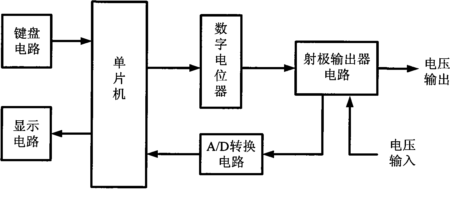
[0011] Attached below figure 1 , figure 2 The present invention will be described in detail.

[0012] The block diagram of the emitter follower circuit that can automatically adjust the static operating point is shown in figure 1 As shown, the circuit diagram of the emitter follower that can automatically adjust the static operating point is shown in figure 2 shown. exist figure 1 Among them, the single-chip microcomputer is connected with the digital potentiometer through serial communication, multiple adjustable resistors of the digital potentiometer are connected with the emitter follower circuit, and the static working point of the emitter follower circuit is determined by multiple adjustable resistors , the keyboard circuit is connected to the single-chip microcomputer and can be used to key in the corresponding static operating point value or other information, the display circuit is connected to the single-chip microcomputer to display the set static operating poi...


PUM


Abstract

The invention discloses an emitter follower circuit capable of automatically regulating a quiescent operation point, belonging to the field of electronic technique application. The emitter follower circuit comprises a singlechip, a digital potentiometer, an emitter follower circuit, an A / D (Analog / Digital) conversion circuit, a keyboard circuit and a display circuit, wherein the keyboard circuit and the display circuit are connected with the singlechip; resistors R2, R3, R4 and R5 are adjustable resistors in the digital potentiometer, and the resistance value of the resistors R2, R3, R4 and R5 can be controlled by the singlechip; the A / D conversion circuit is used for monitoring the value of a quiescent operation point, and the keyboard circuit and the display circuit are used for setting and displaying the value of the quiescent operation point. The invention has the advantages that a plurality of adjustable resistors in the digital potentiometer are used to replace the common potentiometer manually adjusted, so that the resistance value of the digital potentiometer is controlled by the singlechip, and the quiescent operation point of the emitter follower circuit can be adjusted in real time.

Description

technical field [0001] The invention is an emitter follower circuit capable of automatically adjusting a static working point, which belongs to the application field of electronic technology and can be used in electronic technology experimental equipment, various instruments and meters and control units. Background technique [0002] At present, the electronic technology experimental training equipment of some university electrical students and the single-chip experimental training equipment are independent of each other, the experimental training resources are not organically combined, the utilization rate of experimental resources is low, it is a waste of resources, and the knowledge learned by students is not effective. , Consolidated and applied continuously and comprehensively, the emitter follower circuit is one of the contents of the experimental training of the "Electronic Technology" course for university electrical students; in the control units of some instruments ...

Claims


Application Information

Patent Timeline
Patent Type & Authority Applications(China)
IPC IPC(8): G05B19/042
Inventor 张念鲁杨春兰
Owner BIOCHEM ENG COLLEGE OF BEIJING UNION UNIV
Why Eureka
Try Eureka