
Rough yarn conveying device

A technology of transportation device and roving, which is applied in the direction of transportation and packaging, conveyors, mechanical conveyors, etc. It can solve the problems of easily damaged workshop floor, misplaced roving, and affecting product quality, so as to avoid fuzzing, improve economic benefits, The effect of reducing the number of workers

Inactive Publication Date: 2011-04-06
ZHONGHUA GRP
View PDF6 Cites 8 Cited by
  • Summary
  • Abstract
  • Description
  • Claims
  • Application Information

AI Technical Summary

Problems solved by technology

When using a transfer vehicle to transport the roving, it takes a lot of manpower, and because of the dense machinery and equipment, it is easy to transport the roving to the wrong position due to human factors, which not only increases the production cost, but also is not conducive to production efficiency. promotion
In addition, due to the long-term use of the transfer vehicle for transportation, the wheels of the transfer vehicle and the ground wear relatively concentrated, which is easy to damage the workshop floor. In order to maintain a clean and normal production environment, the ground needs to be repaired, which undoubtedly increases the cost.
Moreover, in the process of transportation, it is easy to cause roving pollution and fluff, which will affect the quality of the product

Method used


Image

  • Rough yarn conveying device
  • Rough yarn conveying device
  • Rough yarn conveying device

Examples


Embodiment Construction

[0012] In order to make those skilled in the art understand, the present invention will be further described below in conjunction with the accompanying drawings.

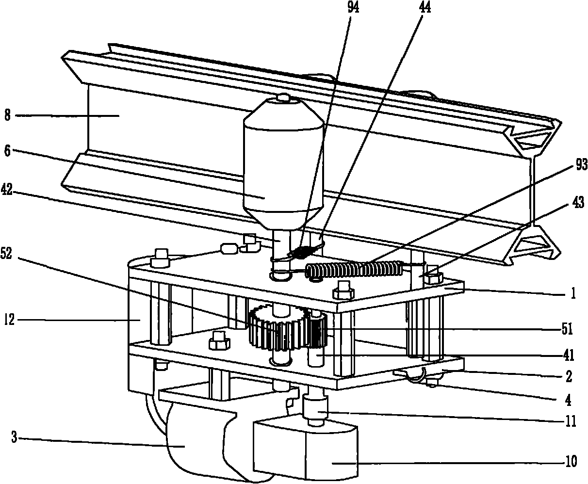
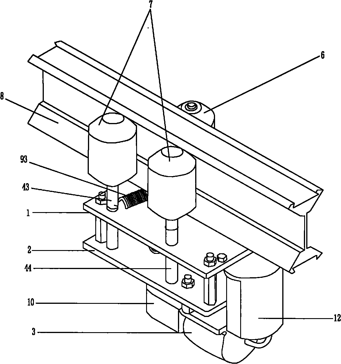
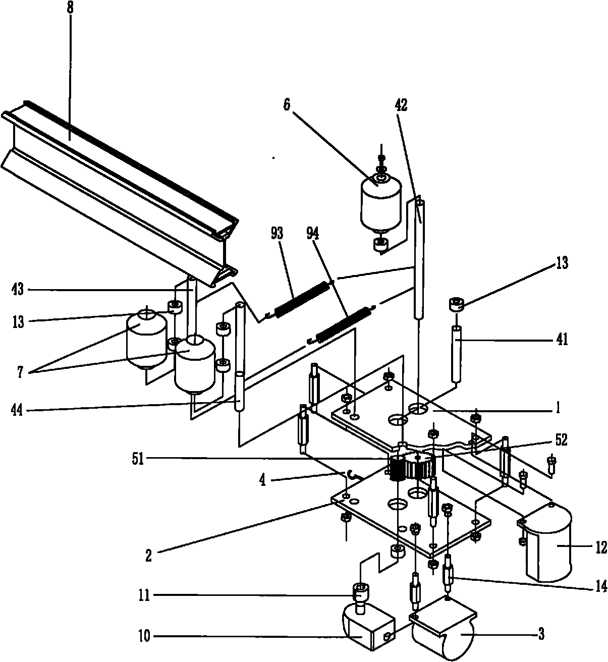
[0013] as attached figure 1 , 2 As shown in , 3, a kind of roving conveying device comprises the upper frame plate 1 and the lower frame plate 2 fixedly attached to each other, the upper frame plate 1 and the lower frame plate 2 are fixedly connected by connecting columns, and also includes a fixed The motor 3 that is installed on the bottom surface of the lower frame plate 2 and the transmission mechanism that is connected with the motor 3, and the track 8 that is connected with the transmission mechanism that is located at the upper frame plate 1 top. This transmission mechanism comprises driving transmission shaft 41, passive transmission shaft 42 and the driving gear 51 and the driven gear 52 that are positioned between upper frame plate 1 and lower frame plate 2, and the lower end of main transmission shaft 41...


PUM


Abstract

The invention relates to a rough yarn conveying device. The device comprises an upper frame plate, a lower frame plate, a motor, a transmission mechanism, a rail and eccentric auxiliary shafts, wherein the upper frame plate and the lower frame plate are fixedly connected through a connecting column; the motor is arranged on the bottom surface of the lower frame plate; the transmission mechanism is connected with the motor and comprises a driving transmission shaft, a driven transmission shaft, and a driving gear and a driven gear which are positioned between the upper frame plate and the lower frame plate; the lower end of the driving transmission shaft passes through the lower frame plate and is connected with the motor, and the upper end of the driving transmission shaft passes through the driving gear and is fixedly connected with the driving gear; the lower end of the driven transmission shaft movably passes through the lower frame plate, and the upper end of the driven transmission shaft passes through the upper frame plate; the driven gear is fixedly sleeved on the driven transmission shaft; the top end of the driven transmission shaft is fixedly provided with a driving wheel; the eccentric auxiliary shafts pass through the upper frame plate and the lower frame plate respectively, and the top ends of the eccentric auxiliary shafts are fixedly provided with auxiliary wheels; and the rail is arranged above the upper frame plate, connected with the transmission mechanism and hung between the driving wheel and the auxiliary wheels. The rough yarn conveying device reduces labor intensity and optimizes the quality of finished products.

Description

technical field [0001] The invention relates to a roving transport device in the textile industry. Background technique [0002] In the existing textile industry, such as in the production workshop of a cotton spinning mill, a large amount of roving needs to be transported from the roving production station to the spun yarn production station during the ring spinning production process. To achieve this, it is common practice to transport the roving from the roving production station to the spun yarn production station by means of a transfer vehicle. Since there are generally many machines and equipment installed in the production workshop, in order to save space, these machines and equipment are generally installed densely, and the remaining space on the ground in the workshop is relatively small. When using a transfer vehicle to transport the roving, it takes a lot of manpower, and because of the dense machinery and equipment, it is easy to transport the roving to the wron...

Claims


Application Information

Patent Timeline
Patent Type & Authority Applications(China)
IPC IPC(8): B65G35/00
Inventor 冯承汪去病
Owner ZHONGHUA GRP
Learn More