Lamp holder, illuminating device, display device and television receiving device
A technology for holding parts and holding protrusions is applied in the fields of lighting devices, lamp holders, display devices and television receiving devices, which can solve problems such as falling and achieve the effect of improving acquisition efficiency.
- Summary
- Abstract
- Description
- Claims
- Application Information
AI Technical Summary
Problems solved by technology
Method used
Image

Examples
Embodiment approach 1
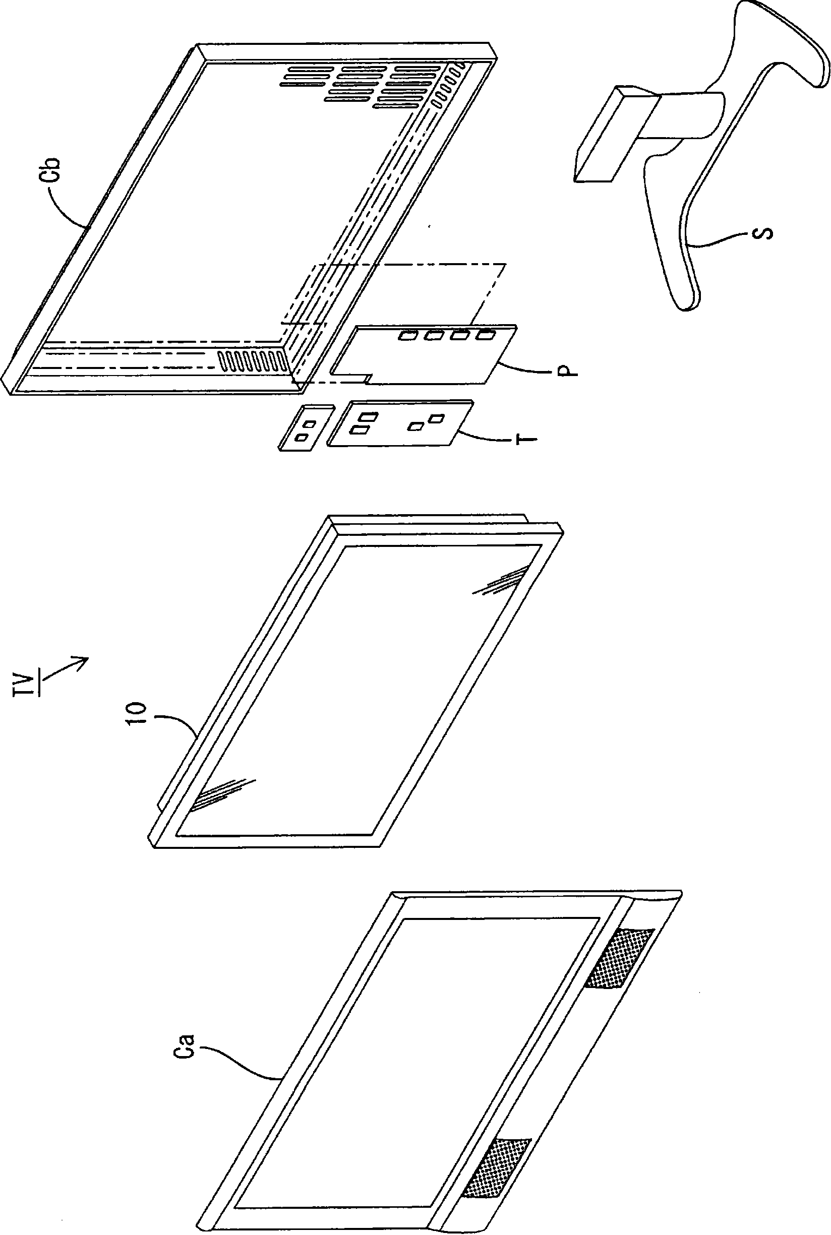
[0118] according to Figure 1 ~ Figure 2 Embodiment 1 of the present invention will be described.
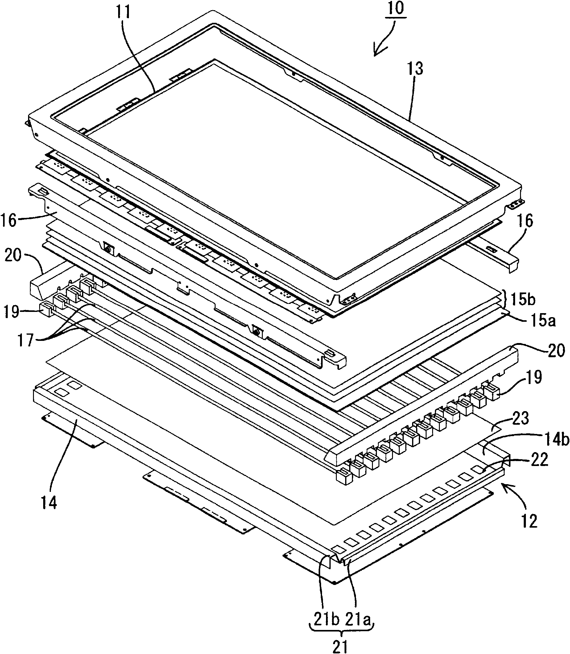
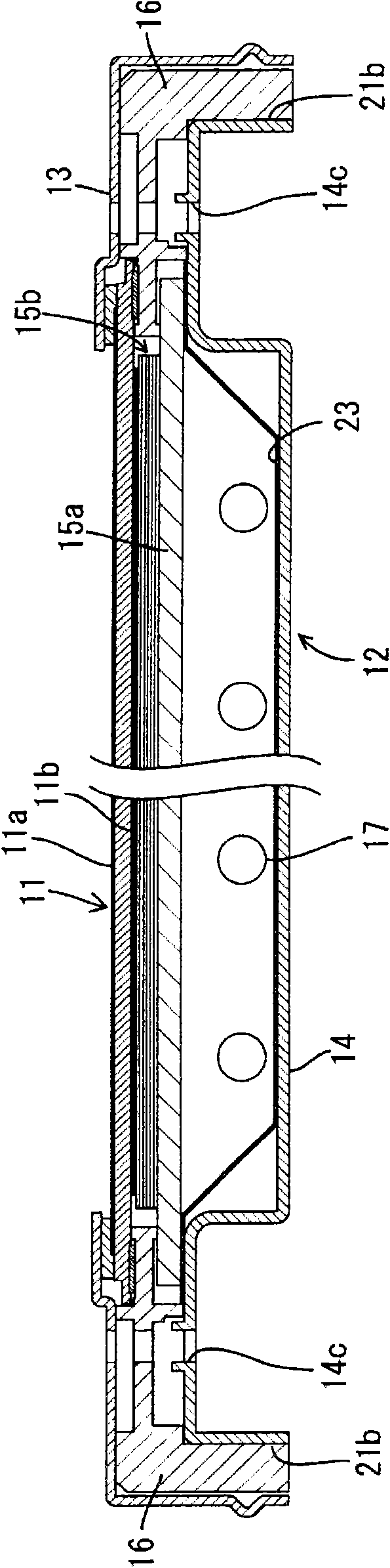
[0119] The television receiver TV of this embodiment is such as figure 1 As shown, it includes: a liquid crystal display device 10 ; two front and back cases Ca and Cb that accommodate the liquid crystal display device 10 ; a power supply P; a tuner T and a stand S. The liquid crystal display device (display device) 10 is configured as a horizontally elongated square as a whole, and is housed in a vertical state. The liquid crystal display device 10 such as figure 2 It has a liquid crystal panel 11 as a display panel and a backlight device (illumination device) 12 as an external light source, and they are integrally held by a frame-shaped bezel 13 or the like. In addition, part of each drawing shows an X-axis, a Y-axis, and a Z-axis, and each axis direction is drawn so that it may become the direction shown in each drawing.
[0120] Next, the liquid crystal panel 11 and the b...
Embodiment approach 2
[0188] pass Figure 22 Embodiment 2 of the present invention will be described. In this second embodiment, the position of the reference line L1-A set on the base 14-A is changed. In this second embodiment, the same reference numerals are used for the parts with the same names as those in the above-mentioned first embodiment, and the suffix -A is added at the end thereof, and repeated descriptions of the structures, operations and effects are omitted.
[0189] As described in Embodiment 1, the diffuser plate (not shown) incorporated in the backlight unit 12-A is a member that may undergo thermal expansion or contraction, but which part of the diffuser plate is easy to expand and contract depends on the lighting. Heat distribution when the backlight unit 12-A is turned off. If the heat distribution is uniform, the closer the diffuser is to the center of the screen, the easier it is to expand and contract. However, if the heat distribution is biased, the part of the diffuser t...
Embodiment approach 3
[0193] pass Figure 23 or Figure 24 Embodiment 3 of the present invention will be described. In Embodiment 3, the arrangement of the cold cathode tubes 17-B and the like in the chassis 14-B and the arrangement of the reference line L-B are changed. In this third embodiment, the parts with the same names as those in the first embodiment are given the same reference numerals with the suffix -B added at the end, and repeated descriptions of the structures, functions and effects are omitted.
[0194] Cold cathode tube 17-B as Figure 23 As shown, they are attached to the base 14-B in a state where the longitudinal direction thereof coincides with the short side direction of the base 14-B (diffuser plate), and a plurality of them are arranged parallel to each other. Lamp clips 18-B for holding these cold cathode tubes 17-B are attached to the base 14-B in a state where the longitudinal direction of the main body 27-B coincides with the longitudinal direction of the base 14-B (d...
PUM
 Abstract
Description
Claims
Application Information
 - R&D
- Intellectual Property
- Life Sciences
- Materials
- Tech Scout
- Unparalleled Data Quality
- Higher Quality Content
- 60% Fewer Hallucinations
Browse by: Latest US Patents, China's latest patents, Technical Efficacy Thesaurus, Application Domain, Technology Topic, Popular Technical Reports.
© 2025 PatSnap. All rights reserved.Legal|Privacy policy|Modern Slavery Act Transparency Statement|Sitemap|About US| Contact US: help@patsnap.com