Clothes drier
A drying machine and clothing technology, which is applied to household clothes dryers, washing machines with containers, textiles and papermaking, etc., can solve the restriction of increasing the circulation air volume, cannot fully ensure the air volume for drying, and cannot efficiently dry objects Drying and other problems, to achieve the effect of drying efficiency
- Summary
- Abstract
- Description
- Claims
- Application Information
AI Technical Summary
Problems solved by technology
Method used
Image
Examples
no. 1 Embodiment approach
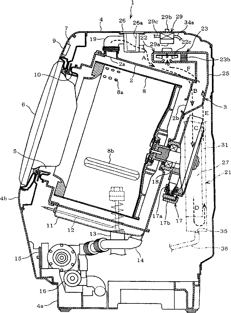
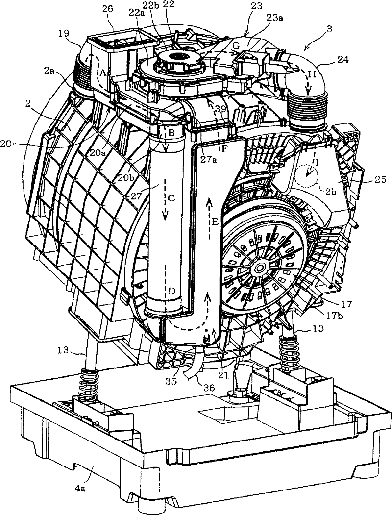
[0027] Hereinafter, for the first embodiment shown by applying the present invention to a drum type washing and drying machine, refer to Figure 1 to Figure 4 Be explained. in, figure 2 It is a longitudinal sectional side view showing the overall configuration of the washing and drying machine 1, image 3 It is a perspective view which shows the outer tank 2, the circulation path 3, etc. which are the mechanism part inside a main body mentioned later, and demonstrates the whole structure of the washing-drying machine 1 with reference to these.
[0028] In addition, this washing and drying machine 1 functions as a washing machine when performing a washing operation and a dehydrating operation, and functions as a clothes dryer when performing a drying operation.
[0029] as shown in figure 2 Specifically, the main body 4 that forms the outline of the washing and drying machine 1 is substantially in the shape of a rectangular box, and a bottom plate 4a is provided at the bot...
no. 2 Embodiment approach
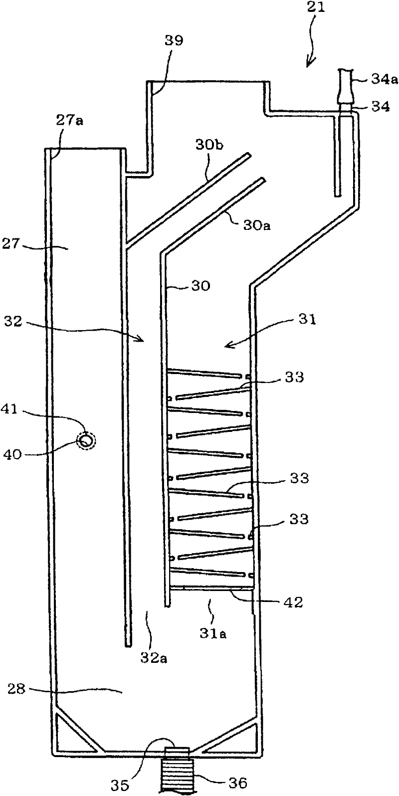
[0115] Figure 5 is the second embodiment of the present invention and figure 1 Quite a graph. as shown in Figure 5 Groundly, the inlet side of the heat exchange unit 21 that constitutes the heat exchanger 31 passage and the branch passage 32 is connected to the vertical pipe 51, and the short-circuit passage 52 that is connected to the drying air outlet 39 side of the heat exchange unit 21 and the heat exchanger 31 is formed. On the side wall top of the downpipe 51.
[0116] In the present embodiment, since the downpipe 51 is integrally formed with the heat exchange unit 21 and its side wall is a common wall, the short-circuit path 52 can be formed only by forming a communication hole.
[0117] Next, regarding the operation of the drying operation in this embodiment, also refer to the description of the same configuration. figure 2 , image 3 to explain.
[0118] Part of the drying air (dotted arrow C) flowing downward in the drooping tube 51 flows into the short-circ...
no. 3 Embodiment approach
[0128] shown in Figure 6 ~ Figure 10 The third embodiment is characterized in that it is particularly provided with a baffle plate 62 (the passage can be changed) so that the cross-sectional area of the branch passage 32 of the heat exchange unit 61 (corresponding to the heat exchange unit 21 in the first embodiment) can be changed. unit), which will be described in detail below.
[0129] Image 6 is the third embodiment of the present invention and figure 1 Quite a graph. Figure 7 It is an air volume characteristic diagram showing the relationship between the opening degree of the branch passage 32 and the air volume of the drying air flowing into the passage of the heat exchanger 31 and the branch passage 32 . Figure 8 It is a characteristic diagram showing the respective changes in the drying air characteristics and the opening degree of the distribution passage 32 accompanying the progress of the drying operation. Figure 9 It is a characteristic diagram showing t...
PUM
 Abstract
Description
Claims
Application Information
 - Generate Ideas
- Intellectual Property
- Life Sciences
- Materials
- Tech Scout
- Unparalleled Data Quality
- Higher Quality Content
- 60% Fewer Hallucinations
Browse by: Latest US Patents, China's latest patents, Technical Efficacy Thesaurus, Application Domain, Technology Topic, Popular Technical Reports.
© 2025 PatSnap. All rights reserved.Legal|Privacy policy|Modern Slavery Act Transparency Statement|Sitemap|About US| Contact US: help@patsnap.com


