Method for determining inductance value at alternating side of shunt active power filter
A technology of power filter and determination method, which is applied to active power filter, AC network to reduce harmonics/ripple, harmonic reduction device, etc., to achieve the effect of improving compensation effect and improving design accuracy
- Summary
- Abstract
- Description
- Claims
- Application Information
AI Technical Summary
Problems solved by technology
Method used
Image
Examples
Embodiment Construction
[0023] The present invention will be further described below in conjunction with the accompanying drawings and embodiments.
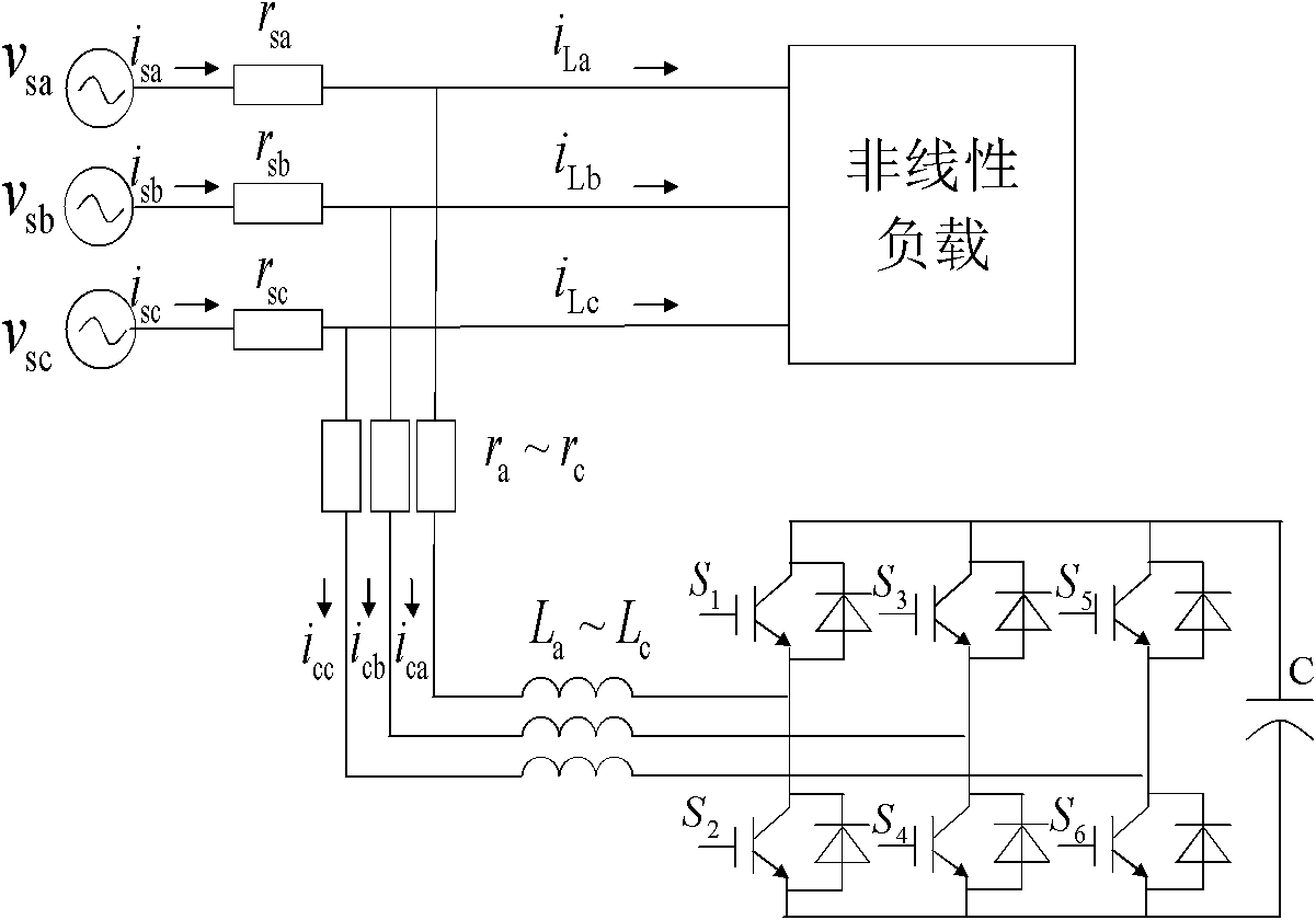
[0024] A typical shunt active power filter such as figure 1 Shown (take three-phase as an example). u in the picture sa ~ u sc i sa ~i sc and r sa ~ r sc Respectively represent the voltage, current and internal resistance of the power supply side; i ca ~i cc and r a ~ r c represent the current and resistance of the compensation side, respectively. L a ~ L c is the AC side inductance. the s 1 ~s 6 are the corresponding six intelligent power modules. C is the DC side capacitance, U dc is the voltage across it.
[0025] According to Kirchhoff's law, the state space equation of APF is established:
[0026] di ca dt di cb ...
PUM
 Abstract
Description
Claims
Application Information
 - R&D
- Intellectual Property
- Life Sciences
- Materials
- Tech Scout
- Unparalleled Data Quality
- Higher Quality Content
- 60% Fewer Hallucinations
Browse by: Latest US Patents, China's latest patents, Technical Efficacy Thesaurus, Application Domain, Technology Topic, Popular Technical Reports.
© 2025 PatSnap. All rights reserved.Legal|Privacy policy|Modern Slavery Act Transparency Statement|Sitemap|About US| Contact US: help@patsnap.com


