
Engine air track mounting bracket with vibration attenuation function

A technology for mounting brackets and engines, applied to engine components, combustion engines, machines/engines, etc., can solve the problems of complex assembly, unfavorable mass production, and many parts, and achieve the effect of reducing production costs and improving competitiveness

Inactive Publication Date: 2010-12-15
CHONGQING CHANGAN AUTOMOBILE CO LTD
View PDF4 Cites 0 Cited by
  • Summary
  • Abstract
  • Description
  • Claims
  • Application Information

AI Technical Summary

Problems solved by technology

[0003] At present, for engines that use natural gas, the installation of the gas rail is mainly fixed by rigid connection with the bracket. In order to make the gas rail and the mounting bracket achieve a good mode, it is necessary to add a lot of ribs or other Strengthening measures, but the ribs are limited by the space and the position of the bolts, it is often difficult to achieve the ideal state, and too many ribs will also increase the cost of the process, and the appearance of the product will also become untidy and beautiful. Sexuality is greatly discounted, which has an adverse effect on the sales of the product
[0004] The patent document with the patent number ZL 200520142743.9 discloses an intake pipe damping bracket assembly, which uses a damping unit to install on the bracket through bushings and bolts. This method has a complicated structure and many parts, resulting in The assembly is complicated, which is not conducive to mass production, and the cost is high, which is not conducive to the promotion of other vibration-absorbing structures.

Method used


Image

  • Engine air track mounting bracket with vibration attenuation function
  • Engine air track mounting bracket with vibration attenuation function
  • Engine air track mounting bracket with vibration attenuation function

Examples


Embodiment Construction

[0015] The structure of the present invention is described in detail below in conjunction with accompanying drawing:

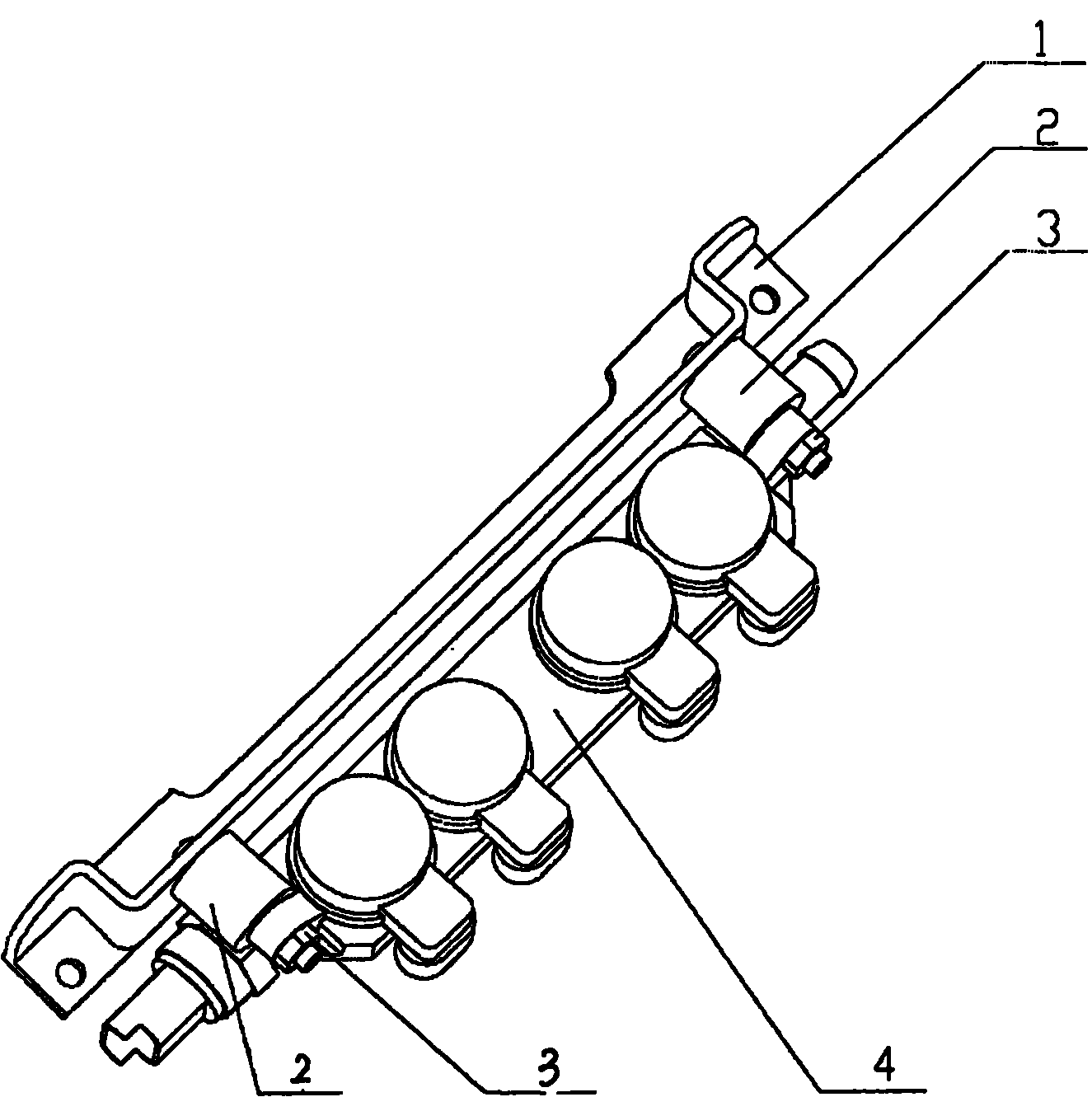
[0016] see figure 1 , the engine air rail mounting bracket includes a bracket 1 and an air rail 4, and the two ends of the air rail 4 are connected to the bracket 1 through a damping unit 2.

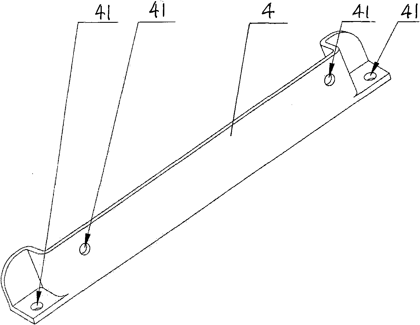
[0017] see figure 2 , the bracket 1 is in the shape of a strip, and there are mounting holes 41 at both ends thereof, which are respectively used for mounting on the engine and mounting the damping unit 2 .

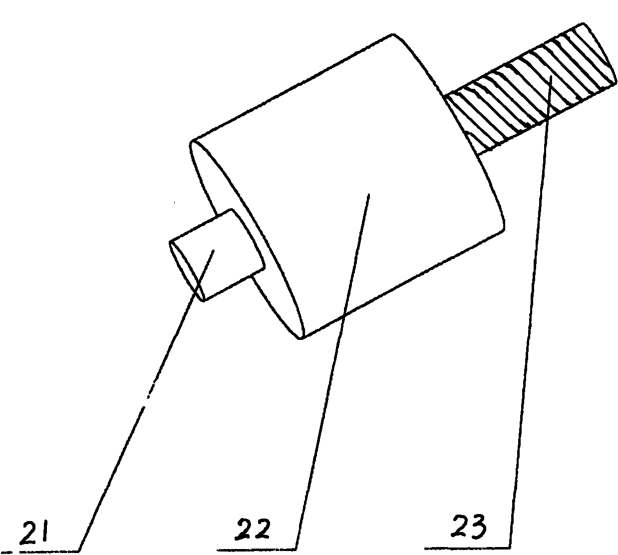
[0018] like image 3 and Figure 4 As shown, the damping unit is made up of a metal polished rod 21, a metal screw 22 and a rubber damping block 23, the rubber damping block 23 is a cylinder, and one end of the metal polished rod 21 and the metal screw 22 is embedded in the rubber damping block 23 respectively. Both ends, but not through the rubber damping block 23, the other ends of the metal polished rod 21 and the metal screw 22 are exposed respectively, and...


PUM


Abstract

The invention provides an engine air track mounting bracket with a vibration attenuation function, comprising a bracket and an air track, wherein both ends of the air track are connected with the bracket; the bracket is arranged on an engine; both ends of the air track are connected with the bracket through a vibration attenuation unit, and the vibration attenuation unit comprises a metal polish rod, a metal screw and a rubber vibration attenuation block; one ends of the metal polish rod and the metal screw are respectively connected to two ends of the rubber vibration attenuation block but both do not pass through the rubber block, and the other ends of the metal polish rod and the metal screw are respectively exposed; the vibration attenuation unit is fixed on the bracket through the exposed end of the metal polish rod; and the exposed end of the metal screw of the vibration attenuation unit is connected with the air track and locked through a nut. The bracket can isolate the vibration of the engine through adopting the vibration attenuation unit so as to avoid transmitting the vibration to the air track of a connected component; and by adopting the scheme, the connected component can achieve the design purposes of reducing the noise, prolonging the service life, and the like without taking measures of increasing many reinforcing ribs, and the like, thus the invention can reduce the production cost and improve the competitive force of a complete vehicle.

Description

technical field [0001] The invention relates to a bracket with vibration damping function, which is used for installing and fixing parts that need to isolate the vibration of an internal combustion engine. Background technique [0002] The internal combustion engine will generate vibration during operation. If the vibration is not isolated but directly transmitted to the components, the components must have a good mode to avoid resonance with the engine and cause component failure. [0003] At present, for engines that use natural gas, the installation of the gas rail is mainly fixed by rigid connection with the bracket. In order to make the gas rail and the mounting bracket achieve a good mode, it is necessary to add a lot of ribs or other Strengthening measures, but the ribs are limited by the space and the position of the bolts, it is often difficult to achieve the ideal state, and too many ribs will also increase the cost of the process, and the appearance of the product...

Claims


Application Information

Patent Timeline
Patent Type & Authority Applications(China)
IPC IPC(8): F02M21/02
CPCY02T10/32Y02T10/30
Inventor 邱阳吴国勇成卫国李春
Owner CHONGQING CHANGAN AUTOMOBILE CO LTD
Learn More