Eureka AIR delivers breakthrough ideas for toughest innovation challenges, trusted by R&D personnel around the world.

Ground well casing capable of preventing mining damage

A surface drilling and casing technology, applied in the direction of drilling pipes, casings, drilling equipment, etc., can solve the problems that affect the smooth drainage of gas and be easily damaged, so as to reduce damage accidents and ensure smooth progress

Active Publication Date: 2010-12-15
CHINA COAL TECH ENG GRP CHONGQING RES INST
View PDF4 Cites 3 Cited by
  • Summary
  • Abstract
  • Description
  • Claims
  • Application Information

AI Technical Summary

Problems solved by technology

[0005] In the prior art, the surface drilling and cementing casing is usually a one-piece structure. According to the above analysis, under the condition of frequent displacement of the overlying strata above the coal seam, the casing of this structure will be subject to many factors such as shearing, tension, compression, torsion, etc. The repeated action of various forces is very vulnerable to damage, which affects the smooth extraction of gas

Method used


Image

  • Ground well casing capable of preventing mining damage
  • Ground well casing capable of preventing mining damage
  • Ground well casing capable of preventing mining damage

Examples


Embodiment 1

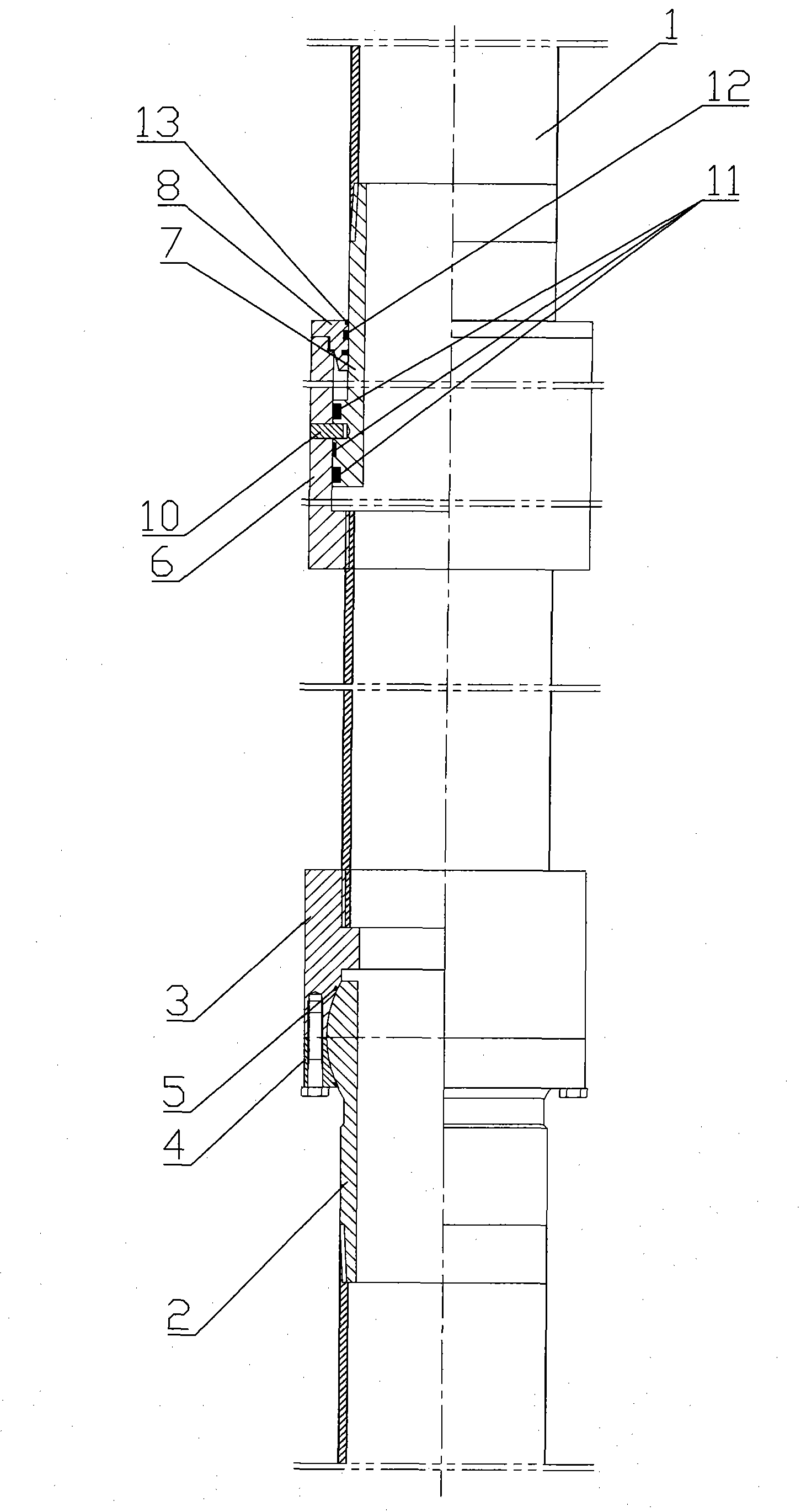
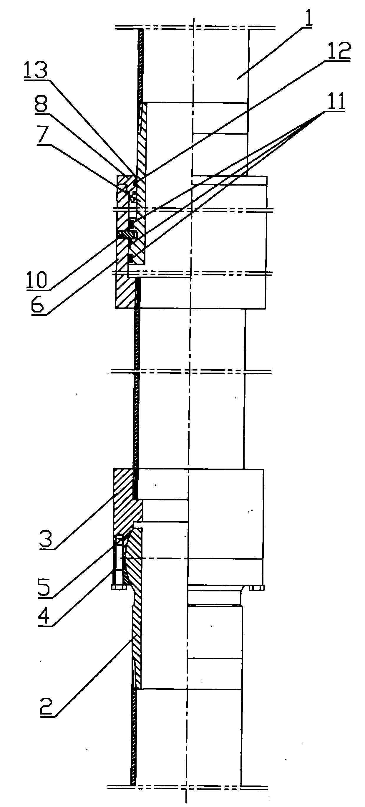
[0021] figure 1 It is a schematic structural diagram of the present invention, as shown in the figure: the ground drilling casing that can prevent mining damage in this embodiment includes a pipe body 1, a deflection joint and an expansion joint, and the pipe body 1 is at least two sections. For example, three sections of pipe body are used. From top to bottom, the first section of pipe body and the second section of pipe body are connected by expansion joints, and the second section of pipe body and the third section of pipe body are connected by deflection joints. According to the analysis results of the displacement, the deflection joint is set at the corresponding depth where the displacement of the rock formation will produce shear and torsion effects on the drilling casing, and the expansion joint is set at the corresponding depth where the displacement of the rock formation will cause tension and compression on the drilling casing. Under the action of the deflection joi...

Embodiment 2

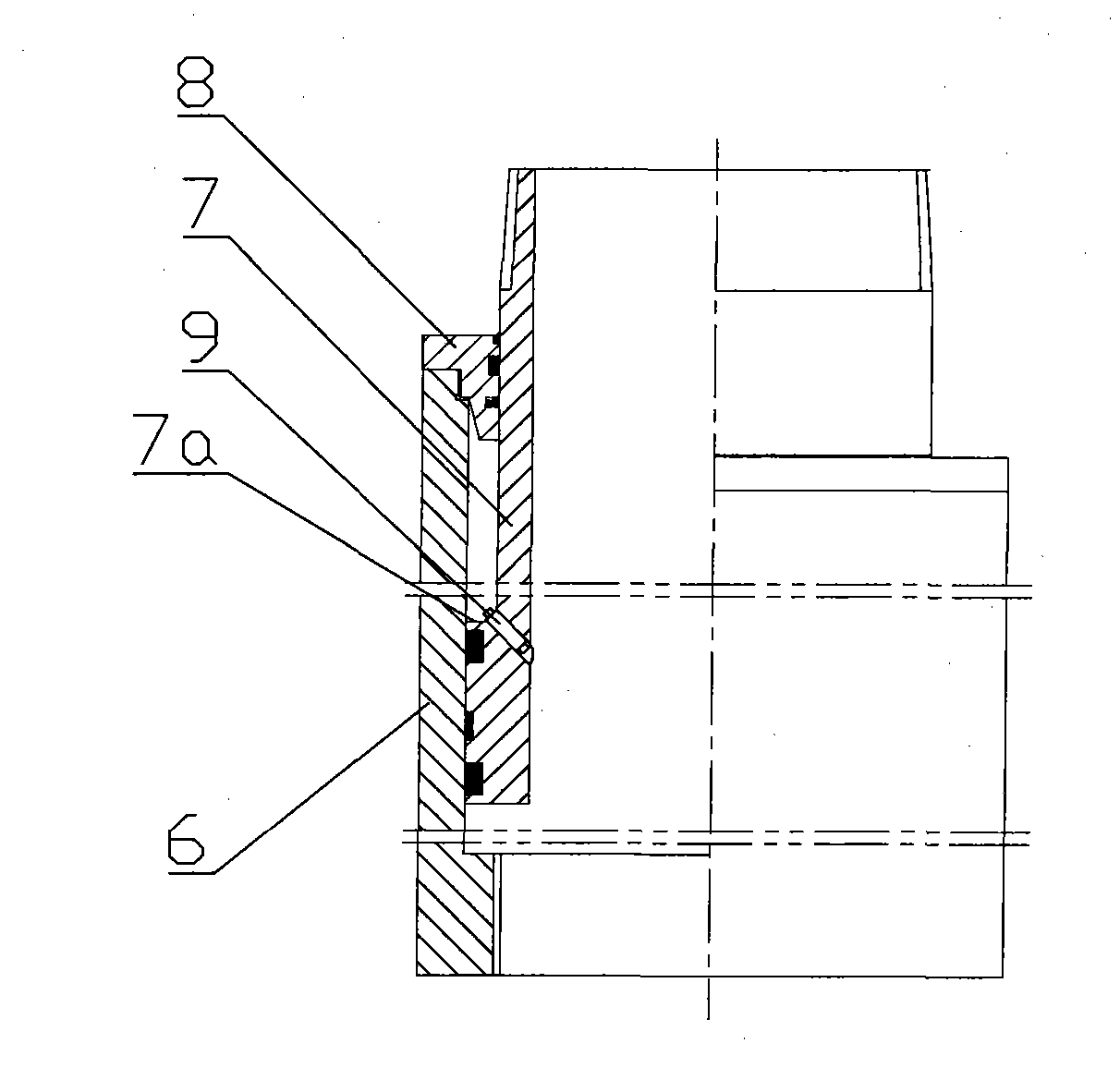
[0027] figure 2 It is a schematic structural diagram of the expansion joint in Embodiment 2 of the present invention, as shown in the figure: in the ground drilling casing that can prevent mining damage in this embodiment, the inner receiving pipe 7 extends into the outer circle of one end of the outer receiving pipe 6 Circumferential steps 7a are arranged on the top, and the expansion joint also includes a guide sleeve 8 that is overlaid on the inner receiving pipe 7 and fixedly connected with the outer receiving pipe 6 in a threaded manner. The guide sleeve 8, the inner wall of the outer receiving pipe 6, and the inner receiving pipe 7. The outer wall and the steps 7a together form a closed space, which is filled with hydraulic medium. A pressure relief valve 9 that communicates with the closed space and the outside world is provided on the wall of the inner receiving pipe 7 to form a locking mechanism. Except for the locking mechanism, the rest are the same structure as th...


PUM


Abstract

The invention discloses a ground well casing capable of preventing mining damage, which comprises at least two casing bodies, a deflection joint and an expansion joint, adjacent casing bodies are connected by the deflection joint or the expansion joint, when in use, according to analysis results of strata displacement, the casing bodies are connected by the deflection joint in the depth corresponding to strata where the casing is easy to cut and twist, the casing bodies are connected by the expansion joint in the depth corresponding to strata where the casing is easy to pull and press, and the casing bodies are connected after the deflection joint and the expansion joint are connected in series in a small depth range corresponding to strata where the casing is easy to not only cut and twist but also pull and press, so that the casing can adapt to strata variation, thus reducing damage accidents of the well casing and guaranteeing smooth gas extraction through the ground well.

Description

technical field [0001] The invention relates to a casing used for well cementing in surface drilling construction, in particular to a flexible surface drilling and cementing casing capable of preventing rock formations from being damaged due to movement. Background technique [0002] During the mining process of the underground coal seam, a pressure relief space will be formed behind it, and a caving zone, a fissure zone and a curved subsidence zone will be formed successively in the vertical direction. The coal seam gas technology in the coal seam area affected by ground drilling and extraction is firstly drilled from the ground to the mining coal seam before the coal seam is mined, and the well is cemented and completed; then the overlying coal rock is affected by the mining of the lower coal seam through the mining of the coal seam "Three vertical belts" are formed in the vertical direction, forming a circulation channel for ground drilling and extraction of gas. The sou...

Claims


Application Information

Patent Timeline
IPC IPC(8): E21B17/00E21B17/08
Inventor 孙东玲林府进陈金华张军孙海涛李日富岳超平隆清明武文宾孙炳兴江万刚晁建伟张玉明贾泉敏刘洋
Owner CHINA COAL TECH ENG GRP CHONGQING RES INST
Why Eureka
Eureka Blog
Learn More