
Address refreshing method based on address refreshing message transmission source node set

A technology of message sending and source node, which is applied in the field of data communication, can solve the problems such as address refresh cannot be solved, and achieve the effect of avoiding repeated refresh of address forwarding table and improving network performance

Inactive Publication Date: 2012-05-23
NANJING UNIV OF POSTS & TELECOMM
View PDF0 Cites 0 Cited by
  • Summary
  • Abstract
  • Description
  • Claims
  • Application Information

AI Technical Summary

Problems solved by technology

[0011] Technical problem: the purpose of the present invention is to provide an address refresh message transmission based on address refresh for the ITU-T G.8032v1 address refresh scheme based on state transfer in the background technology that cannot solve the address refresh problem in the non-reversal recovery mode. Address Refresh Method for Source Node Set

Method used


Image

  • Address refreshing method based on address refreshing message transmission source node set
  • Address refreshing method based on address refreshing message transmission source node set
  • Address refreshing method based on address refreshing message transmission source node set

Examples


Embodiment 1

[0051] Embodiment 1: A single point failure occurs in a certain Ethernet ring network, and then non-reverse recovery is performed, and then another link fails.

[0052] like Image 6 As shown in (a), each node of the ring network starts to be in the IDLE state. When the link fails, nodes C and D periodically send out SF messages (such as Image 6 (b) shown). After the node on the ring receives the SF message for the first time, it finds that the node numbers of node C and node D in the message are not in the set Ω, and then checks the SF message to obtain the address refresh information, the node refreshes the address forwarding table, and sends the node The node numbers of C and node D are added to the set Ω. When the node receives the subsequent SF message, it ignores the address refresh information in the SF message (because the node numbers of nodes C and D are already in the set Ω).

[0053] like Image 6 As shown in (c), when the link failure disappears, nodes C an...

Embodiment 2

[0055] Embodiment 2: A single point of failure occurs in an Ethernet ring network, and then reverse recovery is performed

[0056] like Figure 7 As shown in (a), the link is faulty, and the protection of the link by the ring network is the same as the actual example 2.

[0057] like Figure 7 As shown in (b), nodes C and D continue to block the forwarding of the data packets of the original fault port (the fault disappears now), and periodically send out NR packets. After the control node A receives the NR message, it starts the WTR timer. After the node on the ring receives the message, it reads the node number and finds that the node numbers of nodes C and D are in the set Ω, and then checks the protocol message and finds that there is no address refresh information. Elements with the same node number as node D are deleted.

[0058] like Figure 7 As shown in (c), when the WTR timer expires, the control node blocks the forwarding of data packets on the adjacent ports...


PUM


Abstract

The invention discloses an address refreshing method based on an address refreshing message transmission source node set. The address refreshing method comprises the following steps of: maintaining a set omega by each node of an Ethernet, wherein elements in the set omega are node numbers which correspond to nodes on a source ring for transmitting a protocol message with an instruction refreshingaddress; carrying out analysis on the received protocol message by the node so as to determine whether a new node number is added into the set omega or not; and refreshing an address forwarding tableby the node when the new node number is added into the set omega. The invention can not only avoid the Ethernet protocol message from refreshing the address forwarding table repeatedly under the condition of not increasing nodes, but also solve the address refreshing problem under a non-inversion-recovery mode, thereby ensuring that the Ethernet can converge within 50ms after link switching, and greatly improving the network performance.

Description

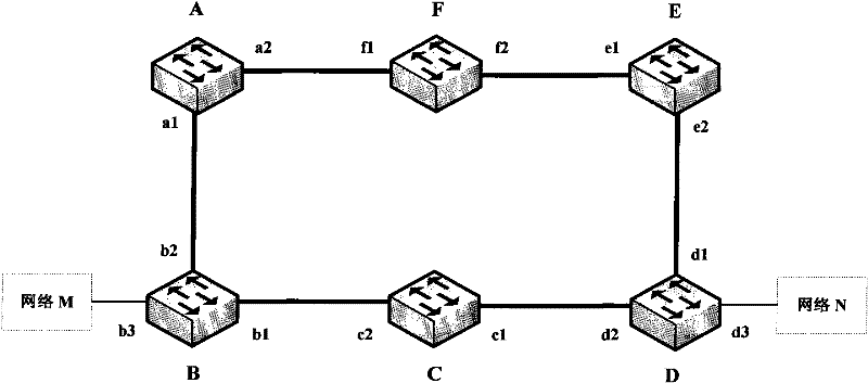
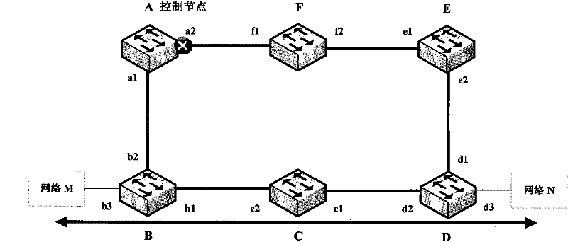
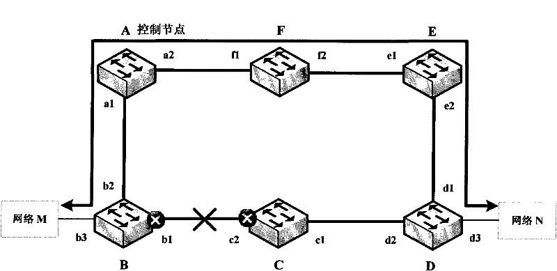
technical field [0001] The invention relates to the field of data communication, in particular to a new method for refreshing addresses of an Ethernet ring network. Background technique [0002] With the development of the Ethernet network in the direction of multi-service bearing, especially some services have higher and higher requirements on the reliability and real-time performance of the network, the Ethernet widely adopts ring networking to improve network reliability. In addition, in the ring protection method, fast protection switching is generally required, reaching less than 50 ms. Currently, such rapid protection switching technologies include RFC3619 of IETF (Internet Engineering Task Force, Internet Engineering Task Force), G.8032v1 of ITU-T (International Telecommunications Union, International Telecommunication Union), and the like. [0003] For example, Ethernet ring network protection technology, such as Figure 1a As shown, nodes A to F are nodes with Ethe...

Claims


Application Information

Patent Timeline
Patent Type & Authority Patents(China)
IPC IPC(8): H04L29/12H04L12/56H04L12/437H04L45/74
Inventor 王斌
Owner NANJING UNIV OF POSTS & TELECOMM
Learn More