
Bicycle riding simulation track and bicycle riding simulation system

A technology for simulating a system and a bicycle, which is used in training equipment for adjusting the cardiovascular system, sports accessories, and mechanical power generation with physical strength. Effect

Inactive Publication Date: 2010-10-20
FUZHOU SUNUR ELECTRONICS TECH
View PDF6 Cites 1 Cited by
  • Summary
  • Abstract
  • Description
  • Claims
  • Application Information

AI Technical Summary

Problems solved by technology

[0005] 1. The energy generated by riding is finally concentrated on the roller in the form of heat energy, which makes the roller and other components generate a lot of heat, which is not conducive to the maintenance and long-term use of the equipment, and the heat is transmitted to the tire that is in contact with the surface of the roller, which is also not conducive to the tire. Conservation and use;
[0006] 2. The above-mentioned equipment needs to adjust the distance between the magnetic device and the roller when adjusting the damping size. In order to achieve the purpose of adjusting the above-mentioned distance, the mechanical structure of the equipment is relatively cumbersome and the operation is complicated;
[0007] 3. The energy generated by cycling is not collected and utilized
[0008] In addition to the above-mentioned methods of providing roller damping, there are also methods such as mechanical friction to provide damping for roller rotation, but there are mechanical wear, complicated equipment, difficult adjustments, and inability to collect energy, which are not conducive to popularization and application.

Method used


Image

  • Bicycle riding simulation track and bicycle riding simulation system
  • Bicycle riding simulation track and bicycle riding simulation system
  • Bicycle riding simulation track and bicycle riding simulation system

Examples


Embodiment Construction

[0028] In order to describe the technical content, structural features, achieved goals and effects of the present invention in detail, the following will be described in detail in conjunction with the embodiments and accompanying drawings.

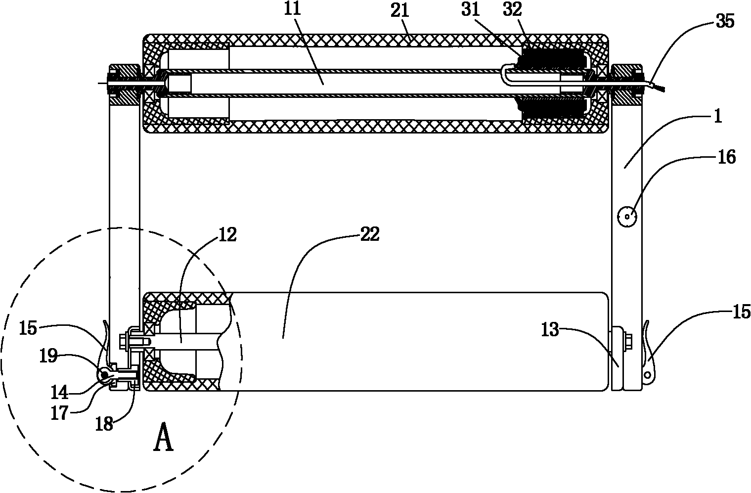
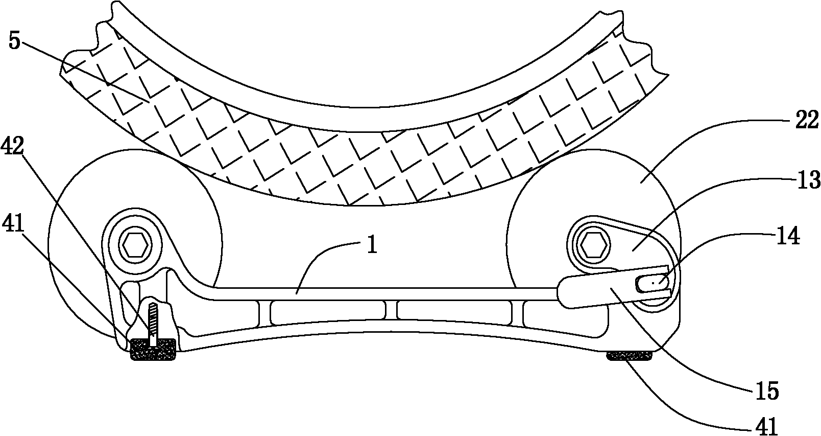
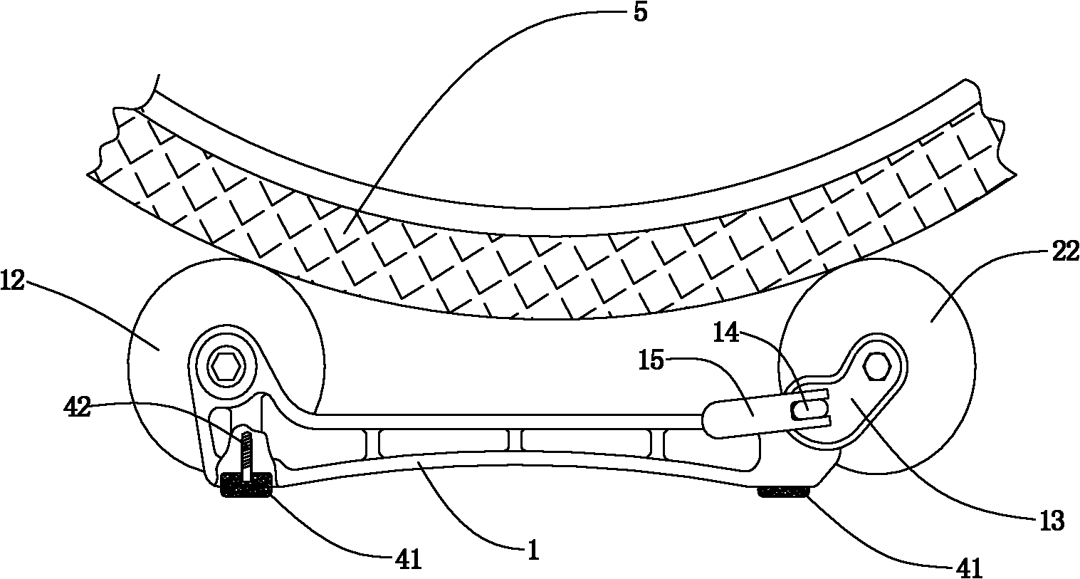
[0029] see figure 1 , figure 2 and image 3 , the present invention provides a bicycle riding simulation track, comprising a bracket 1 and front and rear rollers 21, 22 for placing wheels 5, the front and rear rollers 21, 22 are parallel to each other, and the bracket is provided with front and rear rollers. The rear drum shafts 11, 12, the front and rear drums 21, 22 are in rotation with the front and rear drum shafts 11, 12, and the bicycle riding simulation track is provided with a power generating device, and the power generating device includes a power generation device arranged on the front drum shaft 11 The coil 31 stator on the top and the permanent magnet 32 ​​rotor that is arranged on the inner wall of the front drum in cooper...


PUM


Abstract

The invention discloses a bicycle riding simulation track and a bicycle riding simulation system. The track comprises a bracket and front and rear rollers which are used for placing wheels; the front and rear rollers are parallel to each other; and the bracket is provided with a front roller spindle and a rear roller spindle, and the front and rear rollers are in running fit with the front roller spindle and the rear roller spindle; the bicycle riding simulation track is provided with a generating set; the generating set comprises a stator which is arranged on the front roller spindle or the rear roller spindle, and a rotor which is in running fit with the stator and arranged on an inner wall of the front roller or the rear roller; and the generating set is provided with a power output end. When people ride the bicycle, the generating set generates an electromotive force and outputs the electromotive force through the power output end. Rotational energy is converted into electric energy, an interaction force which is generated by electromagnetic induction is used as damping when the roller rolls to make riding more real, and the energy which is generated on the track is educed by the electric output, so that heating of the bicycle riding simulation track is avoided, and the aim of collecting the energy is fulfilled.

Description

technical field [0001] The present invention relates to a kind of equipment for physical training or fitness exercise, in particular to a kind of bicycle training and exercise equipment. Background technique [0002] Usually, fitness equipment that simulates bicycles is designed to imitate bicycles, and there are few equipment that directly use existing bicycles for fitness or training. The patent No. is "ZL200710121938.9" and is called "bicycle riding balance simulation device". The patent discloses a balance device for the front wheel of a bicycle, which can directly place the self-propelled front wheel on the balance device, and maintain the balance of the vehicle body when directly utilizing the bicycle for training and fitness. In order to cooperate with this type of balancing device, it is also necessary to design a class of riding tracks for placing the rear wheels of bicycles. [0003] In the Chinese patent application "200810071455.7" titled "Magnetic Roller Device...

Claims


Application Information

Patent Timeline
IPC IPC(8): A63B69/16A63B22/08A63B21/005F03G5/02
Inventor 徐峰
Owner FUZHOU SUNUR ELECTRONICS TECH
Learn More