Gear foaming plug

A foaming plug and gear technology, applied in the field of special foaming tools, can solve the problems of inconvenient operation, cumbersome and clumsy, non-sealing, etc., and achieve the effect of simple and light structure, good sealing effect, and low labor intensity

Inactive Publication Date: 2010-07-07
XIANGTAN JIASHUN MACHINERY MFG
View PDF0 Cites 4 Cited by
  • Summary
  • Abstract
  • Description
  • Claims
  • Application Information

AI Technical Summary

Problems solved by technology

Such plug workers are inconvenient to operate, too cumbersome and clumsy
It relies on inclined iron to install 3 pieces of foam plugs at the same time. Due to the accumulation of errors in processing, it is difficult to control and cause leaks. After air leakage and foaming, crystals will flow out; and it will also strain the inner tank of the product and cause rust. Affect the life of the product, and even produce waste products

Method used


Image

  • Gear foaming plug
  • Gear foaming plug

Examples


Embodiment Construction

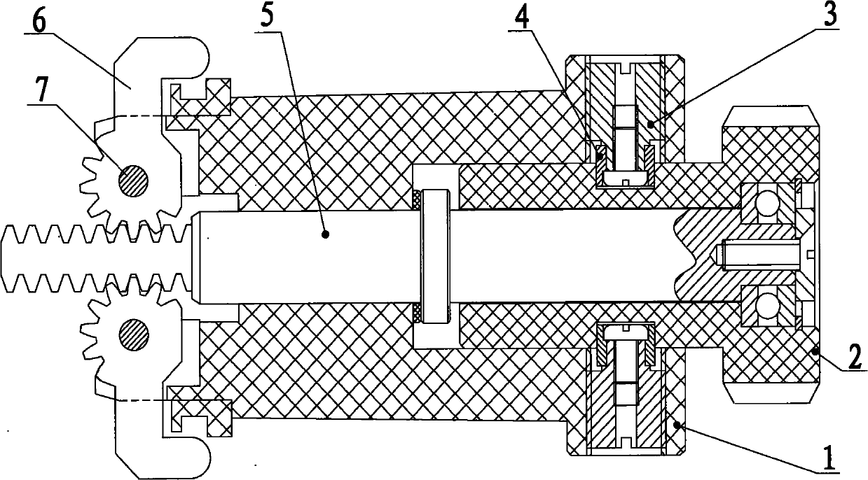
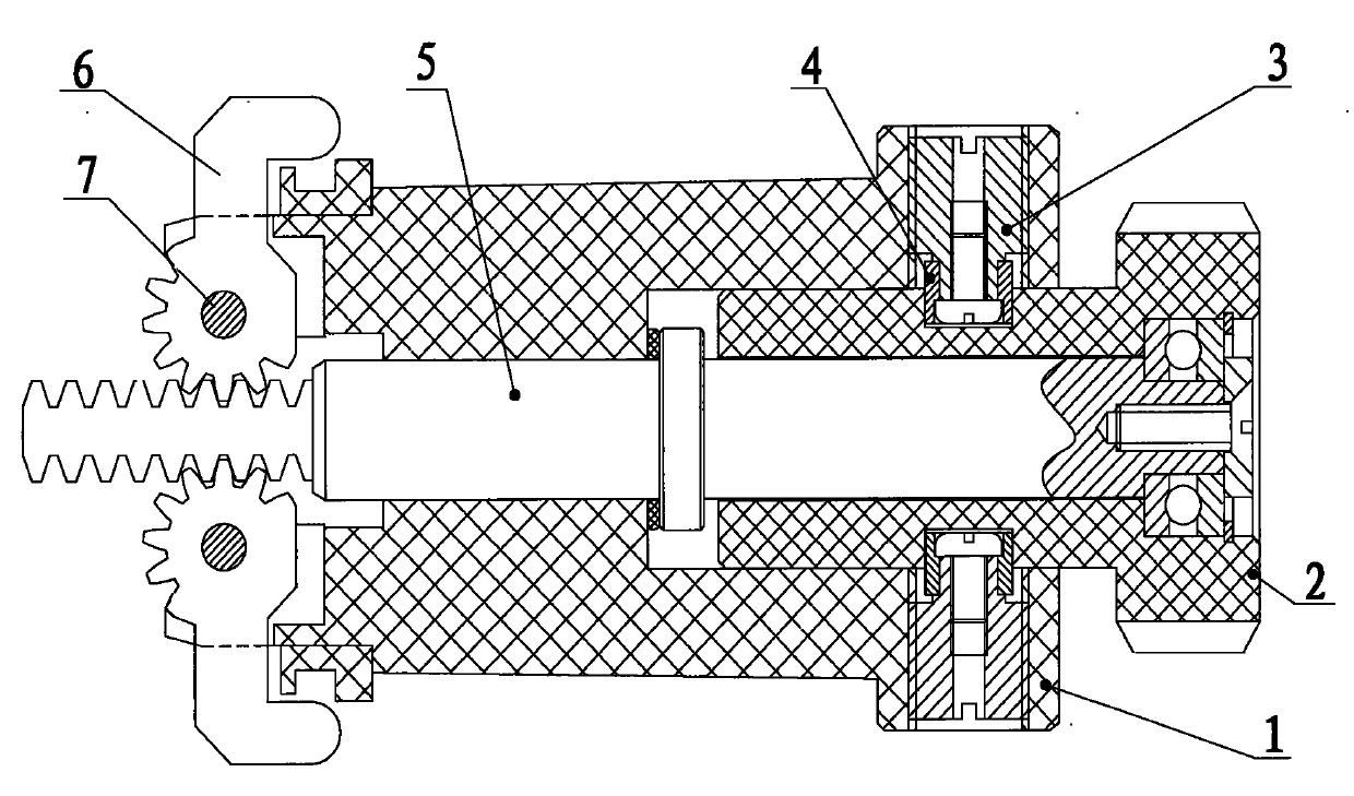
[0010] Such as figure 1 As shown, the gear foam plug of the present invention includes a rotary self-locking mechanism and a rack and pinion mechanism. The rotary self-locking mechanism is composed of a twist sleeve 2, a plug body 1, a screw plug 3 and a roller sleeve 4. The rack rod 5 is composed of a gear claw 6 and a hollow rivet 7. The rack rod 5 is inserted into the hollow plug body 1. One end of the rack rod 5 is a rack, and the other end is connected with a twist sleeve half inserted into the plug body 1. 2. It is connected and fixed. The plug body 1 rests on the two sides of one end of the rack rod 5. A gear claw 6 is movable and fixed through a hollow rivet 7. One end of the gear claw 6 meshes with the rack on the rack rod 5, and the other end For the valgus claw. There are two screw holes on the inner wall of the plug body 1, and a screw plug 3 is installed in the hole, and a rolling sleeve 4 is installed outside the screw plug 3. Realize rotation self-locking.

...


PUM


Abstract

The invention relates to a special foaming tool of a gear foaming plug, which is used on the foaming equipment of a water tank of a solar water heater. The gear foaming plug comprises a rotary self-locking mechanism and a gear and rack mechanism, wherein the rotary self-locking mechanism comprises a torsion sleeve, a plug body, a plug screw and a rolling sleeve, and the gear and rack mechanism comprises a rack pull rod, a gear pawl and a hollow rivet. The gear foaming plug adopts the gear and rack mechanism and a spiral groove structure. The plug only needs to be put into a heat insulation cylinder, and a locking sleeve is inwards pulled and twisted. Because of the single foaming plug, the foaming plug is free from the influence of a processing error, and the plug can be taken out just by pushing and twisting. Compared with a traditional foam plug, the invention has simple, light and convenient structure, simple operation, low labor strength and good sealing effect, can not generate the phenomenon of foam leakage and can not damage a product.

Description

technical field [0001] The invention relates to a special foaming tool-a gear foaming plug used in the foaming equipment of a solar water heater water tank. Background technique [0002] Gear foaming plugs are widely used in the foaming of solar water heater tanks of various specifications, and are also an important part of automatic production in the field of solar water heater foaming. It can not only realize the loading and unloading of a single foaming plug, but also realize multiple Loading and unloading of foam plugs. [0003] The existing foam plug is put into the water storage tank by putting the plug into the water storage tank, then straightening the rod claw of the plug and putting it in, so that the claw is opened, and then the plug is lifted up and the claw is hooked on the inner wall, and installed in the same way 3 pieces of foam plugs are cast with oblique iron. Then pressurize the inner tank to make it expand to a certain extent, and heat it to make the cr...

Claims


Application Information

Patent Timeline
Patent Type & Authority Applications(China)
IPC IPC(8): B29C44/34
Inventor 谭千浬谭振源
Owner XIANGTAN JIASHUN MACHINERY MFG
Why Eureka
Try Eureka