
Dual cell body side rail for automotive vehicles

A technology for motor vehicles and unit vehicles, applied in vehicle components, load-bearing body structures, superstructure sub-assemblies, etc., to solve problems such as excess weight

Inactive Publication Date: 2010-02-03
FORD MOTOR CO
View PDF6 Cites 1 Cited by
  • Summary
  • Abstract
  • Description
  • Claims
  • Application Information

AI Technical Summary

Problems solved by technology

However, maintaining a substantially uniform size and shape for individual frame components can result in a section or component weighing more than it needs to carry

Method used


Image

  • Dual cell body side rail for automotive vehicles
  • Dual cell body side rail for automotive vehicles
  • Dual cell body side rail for automotive vehicles

Examples


Embodiment Construction

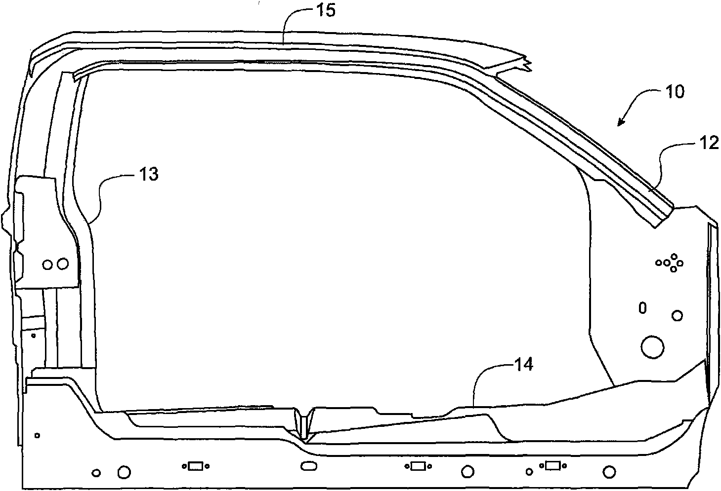
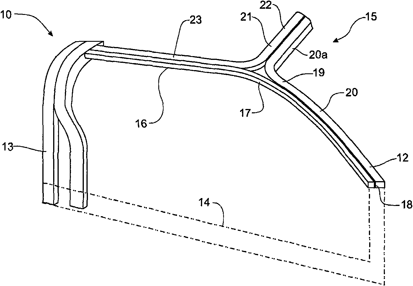
[0026] Referring to the drawings, there can be seen a body side frame structure for a cab of a motor vehicle such as an open pickup truck. For convenience, a left or right reference mark is used, which is determined by standing at the rear of the vehicle, facing the normal direction of forward travel of the vehicle. The body side frame structure 10 includes a front pillar 12 , a rear corner pillar 13 , and a roof rail structure 15 extending between said front and rear pillars 12 , 13 . The frame 10 of the cab is formed with a substantially vertical front pillar (or "A-pillar") 12 extending between a floor member 14 and a roof structure 15 . The rear pillar 13 makes the vehicle body side frame structure 10 substantially form a rectangular structure, and the rear pillar 13 is used for mounting front and rear doors (not shown) through hinges (not shown). Normally, the front doors are hinged on the front A-pillar 12, while the rear B-pillar can support the hinges for the rear doo...


PUM


Abstract

A body side rail construction for an automotive vehicle is formed in a dual cell configuration. A reversed C-shaped channel is welded to the closed section of the conventional roof side rail member toenable the body side rail member to be a smaller section that is less susceptible to buckling as the body side rail member transfers load to the front and rear corner pillars. The C-shaped cross-sectional configuration presents advantages for manufacturing as it can be shaped to provide the attaching brackets and horns for mounting the front header, roof bow, and rear header members to the body side rail without the addition of individual end items to serve this function. From a shipping density standpoint, this design gives maximum structure while maintaining good rack density that enables relatively straight parts to be nested together while still providing the increased section strength required for enhanced roof performance.

Description

technical field [0001] The present invention relates to a vehicle frame of a motor vehicle, and more particularly to a vehicle body side sill structure for increasing the strength of a vehicle roof member, especially a vehicle without a central B-pillar structure. Background technique [0002] A frame of a motor vehicle supports the cab and includes a roof supported by substantially vertical members commonly referred to as uprights. On some vehicles, the roof is usually supported by front and rear pillars, also known as "A-pillars" and "B-pillars". Other vehicle structures may include front and rear pillars, and support pillars located between the front and rear pillars, in which case the front and rear pillars are referred to as "A-pillars" and "C-pillars", The upright between the pillar and the rear pillar is called the "B-pillar". Vehicle frames need to withstand certain stresses related to the strength of the vehicle's roof. Roof strength standards help determine the ...

Claims


Application Information

Patent Timeline
Patent Type & Authority Applications(China)
IPC IPC(8): B62D25/00B62D25/06B62D25/04
CPCB62D25/04B62D25/06B62D23/005
Inventor 勒乌·拉特苏斯约翰·T·里德弗兰克·J·戴依格里高利·S·弗雷德里克希克马特·F·马哈穆德
Owner FORD MOTOR CO
Learn More