Cable joint for connecting a sheathed cable with sheathed part and fixation method of sheathed part

A technology of armored cables and armored parts, which is applied in the field of cable glands for connecting armored cables with armored parts and the fixing of armored parts, which can solve the problems of thread assembly labor, large force, and effort, and achieve Ensure the connection status, improve the efficiency of use, and improve the effect of work efficiency

Inactive Publication Date: 2009-12-09
DONG A BESTECH
View PDF0 Cites 1 Cited by
  • Summary
  • Abstract
  • Description
  • Claims
  • Application Information

AI Technical Summary

Problems solved by technology

However if Figure 5a and Figure 5c As shown, when fastening the armor part 1 such as a large-diameter steel wire on the above-mentioned cable head, because the width of the fastening ring 5 is relatively large, the fastening ring 5 is placed between the joint 7 and the sleeve 8 and clamped. When it is tight, a large force is required to bend the armored part 1 composed of a plurality of thick steel wires with a diameter of more than 1 mm, and the thread assembly of the joint 7 and the sleeve 8 is laborious and requires the use of tools such as wrenches. The aforementioned tools are also labor intensive, thus greatly reducing worker productivity
Moreover, because the width of the fastening ring 5 is large, it is not necessary to disassemble the sleeve 8 again, so it is impossible to confirm whether the armor part 1 is fastened between the joint 7 and the sleeve 8 during assembly.

Method used


Image

  • Cable joint for connecting a sheathed cable with sheathed part and fixation method of sheathed part
  • Cable joint for connecting a sheathed cable with sheathed part and fixation method of sheathed part
  • Cable joint for connecting a sheathed cable with sheathed part and fixation method of sheathed part

Examples


Embodiment Construction

[0023] The term "armoring" used in the present invention refers to the use of metal, plastic, and fabrics to weave meshes in order to strengthen marine cables when ships or drill ships are used in applications where there is a lot of sloshing such as the sea surface Or a non-woven reinforcement made in a non-woven manner as tapes, strips or strands, the term "armoring" being used extensively within the same industry.

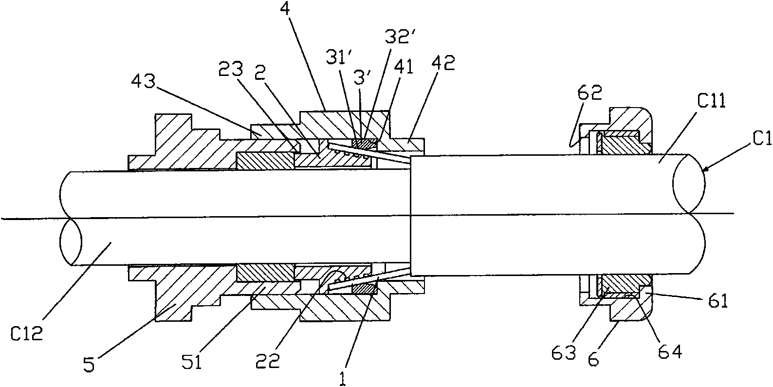
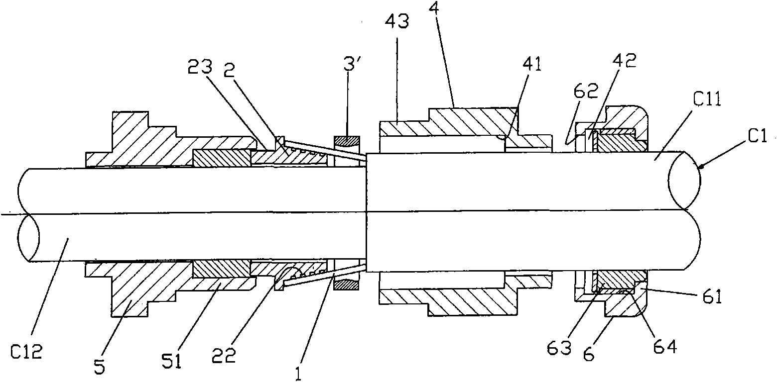
[0024] The armored cable C1 described above includes the armor portion 1 located between the outer sheath C11 and the inner sheath C12. The armor portion 1 of the above-mentioned armored cable C1 can take various forms, such as thicker steel wires such as non-woven steel wires or thin steel wires such as braids, which will not be described in detail in this description.

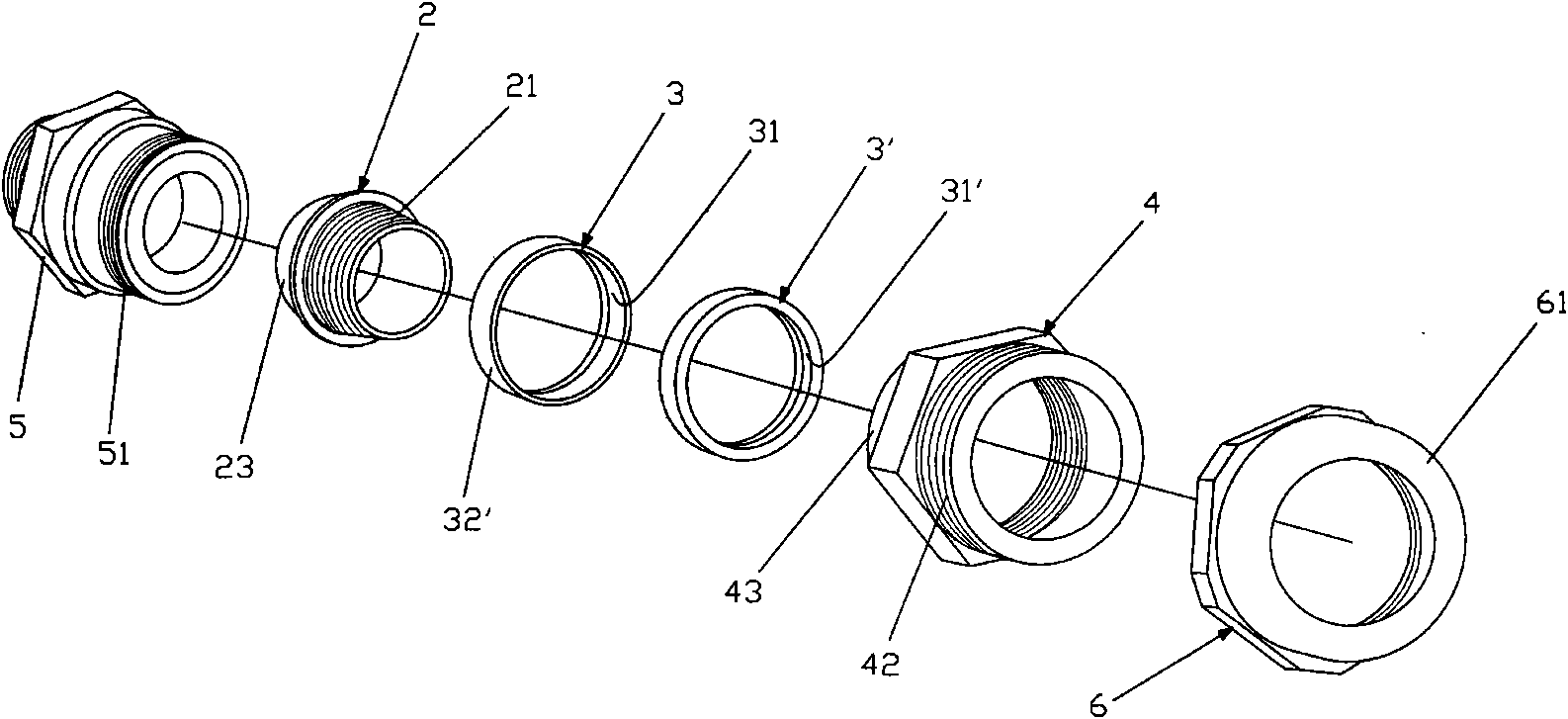
[0025] Such as figure 1 As shown in FIG. 3 , a cable gland A for connecting an armored cable with an armored portion according to an embodiment of the present invention includes: a sleeve 2 ,...


PUM


Abstract

The invention relates to a cable joint for connecting a sheathed cable with a sheathed part. The cable joint comprises a sleeve, a fastening ring and a supporting ring, wherein the outer side of the inclined surface of the sleeve contacts with the inner side of the protruding sheathed part of the sheathed cable with the sheathed part; the fastening ring and the supporting ring are mutually independent and have smaller widths; the inside surfaces of the fastening ring and the supporting ring are respectively provided with inclined surfaces inclined from the center to both sides, and the inclined surface at one side is parallel to the inclined surface of the sleeve; inclined angles of the inclined surfaces at the inner sides of the fastening ring and the supporting ring are similar to an inclined angle of the inclined surface at the outer side of the sleeve; the inclined surface of the fastening ring has a larger radius, and the inclined surface of the supporting ring has a smaller radius; the inside diameters of the fastening ring and the supporting ring are different, and thus the sheathed cable can be easily fixed by a little force in the first assembling and fastening process so that whether the sheathed cable is firmly connected with a steel wire of the sheathed cable or not can be confirmed in the first assembling process; and particularly, a larger-diameter steel wire to be fastened is drawn by the supporting ring so as to obtain double fixation and improve the fastening drawing force.

Description

technical field [0001] The invention relates to a cable head for connecting an armored cable with an armored part and a method for fixing the armored part, in particular to a cable head that can be made of materials such as metal, plastic and fabric, or using tape or strips. The armored cable of the armored portion (armor portion) reinforced by non-woven materials can safely perform the grounding operation of the armored portion, and the armored portion of different sizes can be grounded by changing the position of the fixing ring, thereby improving the efficiency of use. A cable gland for connecting an armored cable of an armored part and a method for fixing the armored part. Background technique [0002] Such as Figure 4 As shown, the inclination angle of the fixed ring 3 of the armored part 1 of the existing armored cable head can only be connected to one thickness, so the user needs to prepare the corresponding cable head for the thickness of the armored part of all cab...

Claims


Application Information

Patent Timeline
Patent Type & Authority Applications(China)
IPC IPC(8): H02G15/00H02G15/02
Inventor 裴准集
Owner DONG A BESTECH
Why Eureka
Try Eureka