
Needle bar reciprocating mechanism of sewing machine

A technology of moving mechanism and sewing machine, which is applied in the direction of needle seat for sewing machine, sewing machine element, control device for sewing machine, etc., can solve problems such as replacement of parts, and achieve the effect of realizing sewing quality and avoiding poor sewing.

Inactive Publication Date: 2009-12-09
JUKI CORP
View PDF1 Cites 2 Cited by
  • Summary
  • Abstract
  • Description
  • Claims
  • Application Information

AI Technical Summary

Problems solved by technology

[0007] However, although the above-mentioned existing needle bar up and down movement mechanism 100 can switch the drive and stop of the needle bar, there are problems such as that parts must be replaced when the needle bar stroke is adjusted.

Method used


Image

  • Needle bar reciprocating mechanism of sewing machine
  • Needle bar reciprocating mechanism of sewing machine
  • Needle bar reciprocating mechanism of sewing machine

Examples


no. 1 Embodiment approach

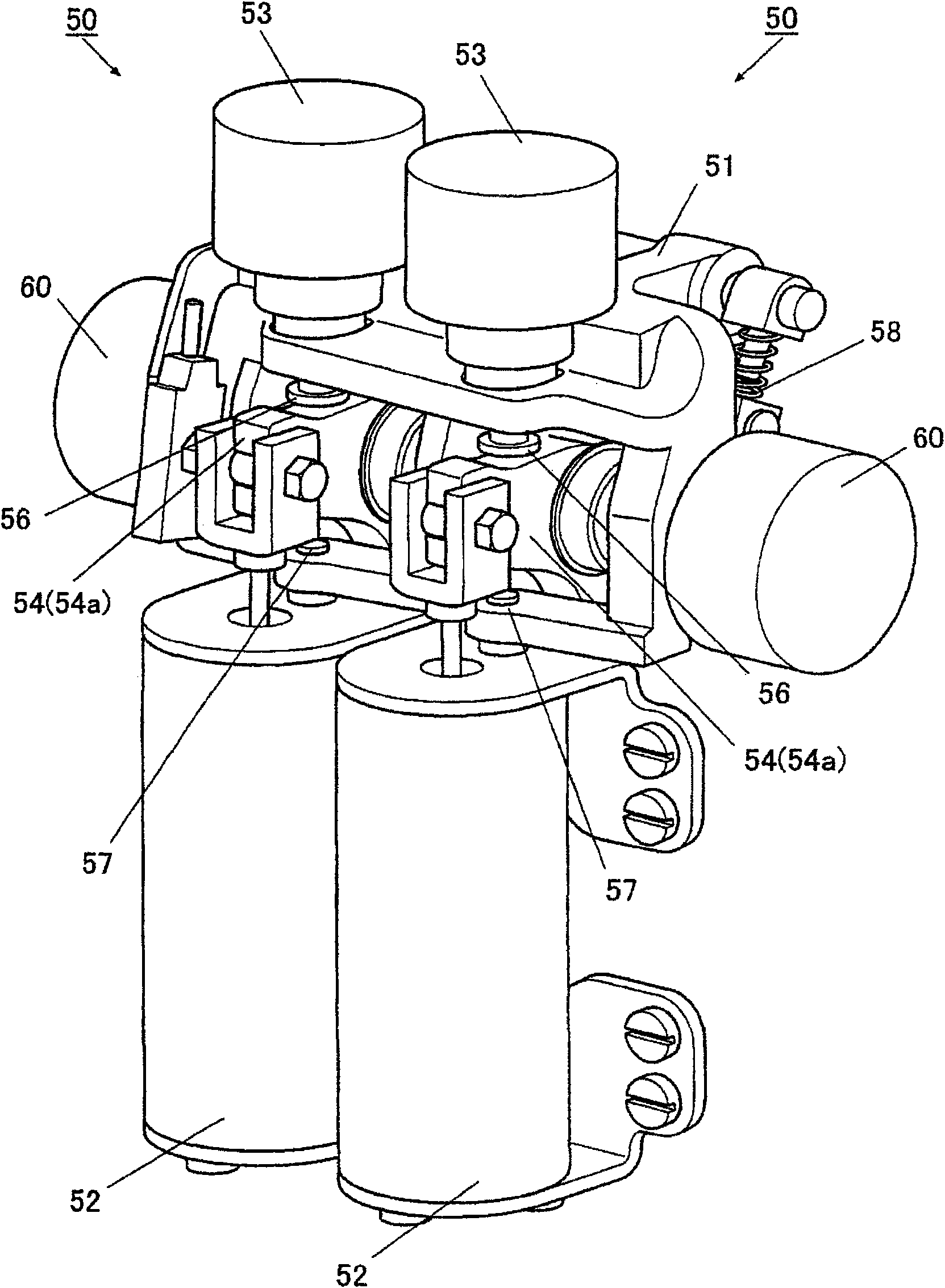
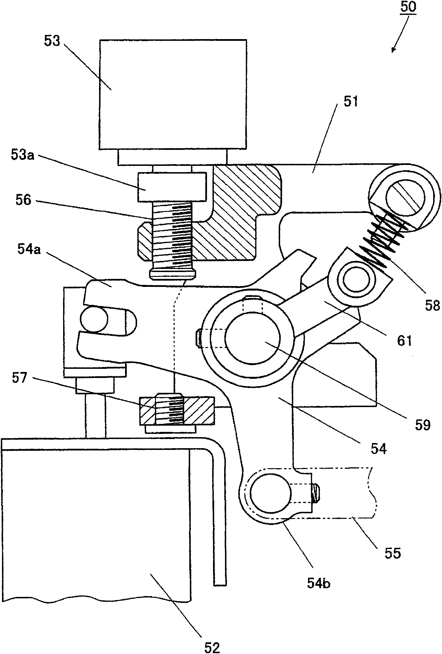
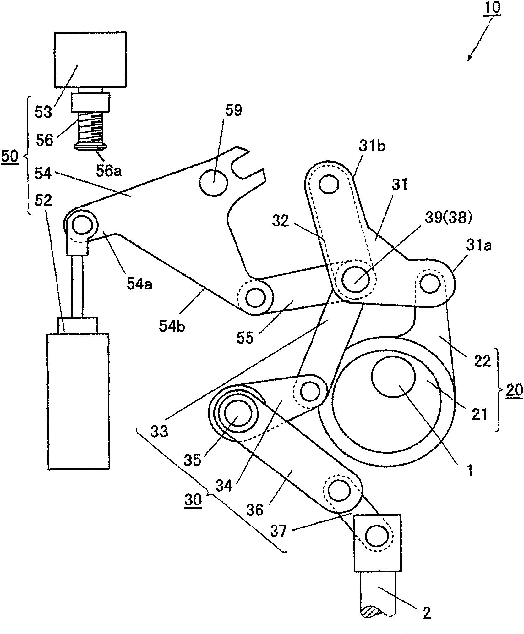
[0032] exist Figure 1 to Figure 4 Among them, the needle bar up and down movement mechanism 10 of the sewing machine has: the main shaft 1, which utilizes the sewing machine motor 3 to perform full-circle rotation; the conversion mechanism 20, which converts the rotation of the main shaft 1, and outputs the reciprocating action; the transmission mechanism 30, which converts the reciprocating action from The conversion mechanism 20 transmits to the needle bar 3 ; and the stroke adjustment mechanism 50 as a movement adjustment mechanism, which adjusts the reciprocating stroke transmitted by the transmission mechanism 30 .

[0033] In addition, since the sewing machine is a double-needle sewing machine, two needle bars 2 are mounted, so the above-mentioned needle bar vertical movement mechanism 10 has two conversion mechanisms 20, a transmission mechanism 30, and a stroke adjustment mechanism 50 respectively, but because they have the same structure, only Describe one of them. ...

no. 2 Embodiment approach

[0068] according to Figure 6 A second embodiment of the present invention will be described.

[0069] In the first embodiment described above, the electromagnetic solenoid 52 and the adjustment motor 53 are provided for each needle bar 130 for adjustment of the needle bar stroke. Instead of this method, in the second embodiment, the needle bar stroke adjustment is performed by one adjustment motor 80 for each needle bar 130 . In the description of the second embodiment, the same components as those of the first embodiment are denoted by the same reference numerals, and detailed description thereof will be omitted.

[0070] In the needle bar vertical movement mechanism 10A of this second embodiment, an adjustment link 81 is provided instead of the aforementioned second bell crank 54 .

[0071] Figure 6 In the illustrated adjustment link 81 , one end side 81 b is connected to the connecting rod 55 , and the other end side is fixedly supported by the support shaft 82 . The ...


PUM


Abstract

The invention provides a needle bar reciprocating mechanism of a sewing machine, capable of adjusting strokes of the needle bar. The mechanism comprises a first double armed crank to obtain power from an electric motor of the sewing machine and rotate around a support shaft; a first transmission connecting bar, connected with the first double armed crank; a second transmission connecting bar, located between the first transmission connecting bar and the needle bar side; a second double armed crank, connected with the first or the second transmission connecting bar and drive a connecting pointto move; and an actuator, connected with the other end of the second double armed crank, comprising an output part that can move at a primary position and a forward position and enable the connectingpoint to move at overlapped position with the support shaft of the first double armed crank and at separated position, and comprising an adjusting motor that can be connected with a first limit stop resisted against the output part of the second double armed crank or the actuator, and adjust the forward position of the output part of the actuator, thus adjust the separated position of the connecting point to adjust strokes of the needle bar.

Description

technical field [0001] The invention relates to a needle bar up and down moving mechanism of a sewing machine capable of adjusting the needle bar stroke. Background technique [0002] Conventionally, as a general sewing machine having a needle bar vertical movement mechanism capable of switching between a needle vertical movement state and a needle stop state, for example, the sewing machine described in Patent Document 1 is known. according to Figure 7 and Figure 8 , to illustrate the needle bar moving mechanism of the sewing machine up and down. [0003] The needle bar up and down movement mechanism 100 has: a main shaft 101, which is rotated by a sewing machine motor; an eccentric cam 102, which is fixedly mounted on the main shaft 101; an eccentric connecting rod 103, which is equipped with the eccentric cam 102 at one end; 104, which connects the first rotating arm 104a with the eccentric link 103; the first transfer link 106, whose one end is connected with the sec...

Claims


Application Information

Patent Timeline
IPC IPC(8): D05B55/14D05B69/00
Inventor 新堀胜
Owner JUKI CORP
Learn More