Shifter mechanism for shift gear box

A technology of shifting mechanism and transmission, applied in mechanical equipment, components with teeth, transmission control and other directions, can solve problems such as difficulty in maintaining accuracy, and achieve the effect of improving accuracy

Inactive Publication Date: 2009-12-02
SCHAEFFLER TECH AG & CO KG
View PDF5 Cites 8 Cited by
  • Summary
  • Abstract
  • Description
  • Claims
  • Application Information

AI Technical Summary

Problems solved by technology

In this arrangement it is difficult to maintain the required accuracy necessary for precise selection or shifting due to the total tolerances created by manufacturing and assembly tolerances of parts and systems

Method used


Image

  • Shifter mechanism for shift gear box
  • Shifter mechanism for shift gear box
  • Shifter mechanism for shift gear box

Examples


Embodiment Construction

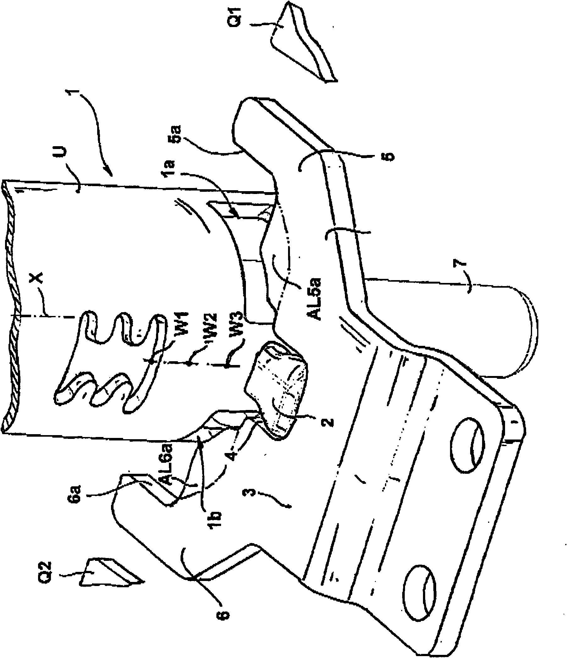
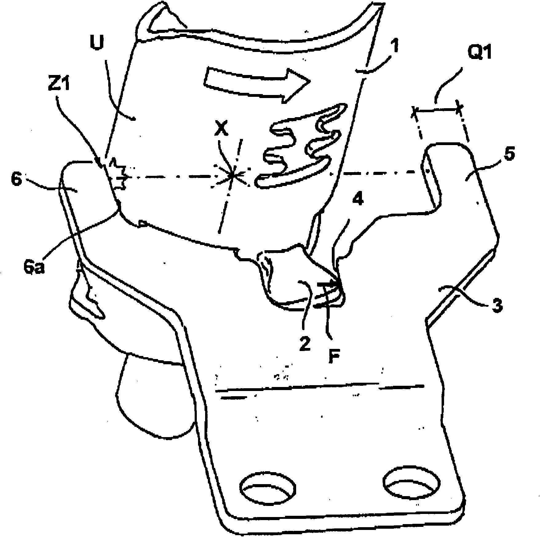
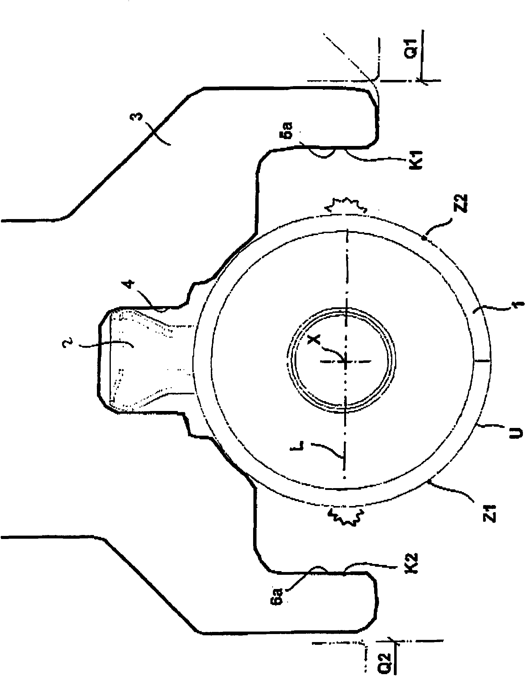
[0022] exist figure 1 The shifting mechanism for a transmission shown in includes a shifting element 1, which is configured as a bush or a hollow shaft and can be moved along its center axis X to different shifting element axial positions W1, W2 , W3. Furthermore, the shifting element 1 can be pivoted in the circumferential direction when the shifting element axial position W1 , W2 , W3 is reached.

[0023] A push rod projection 2 is connected to the shifting element 1 , which push rod projection projects radially beyond the outer circumferential wall U of the shifting element 1 .

[0024] The shifting mechanism also includes at least one, preferably a plurality of shifting arms 3 arranged sequentially along the longitudinal direction of the shifting element 1, the shifting arm has a fork-shaped shift port, and the shift port has a Insert into the engaging groove 4 of the push rod protrusion 2 . The shifting arm 3 is displaceable within the swivel range of the shifting elem...


PUM


Abstract

The present invention relates to a shifter mechanism for a shift gear box, which is constructed to a hollow shaft or a sleeve and is provided with a gear shift lever that comprises a prong inlet groove. According to the invention, the prong is designed at the aspect of prong inner wall so that the prong forms a transverse stop under the cooperation of the hollow shaft or the core rod inserted into the hollow shaft.

Description

technical field [0001] The invention relates to a shifting mechanism for a transmission according to the preamble of claim 1 . Background technique [0002] The invention applies to all movable shifting elements, such as shift forks, selector levers and selector slides, via which actuating forces or movements are transmitted and which have for this purpose One or more pushrod projections are an actuating element in the form of a selector finger, which engages in a fork-shaped shift opening and, when actuated, causes a corresponding linear movement of the shifting element. This movement is usually limited by end stops in the transmission, for example to avoid incorrect gear changes. The stop is formed on the housing. In such an arrangement, due to the overall tolerances resulting from manufacturing and assembly tolerances of the parts and systems, it is difficult to maintain the accuracy required for precise selection or shifting. A shift mechanism of this type is known fr...

Claims


Application Information

Patent Timeline
Patent Type & Authority Applications(China)
IPC IPC(8): F16H63/34F16H63/20
CPCF16H63/20F16H2063/322F16H63/30F16H2061/242F16H2063/3086
Inventor 卡劳斯·克雷默约亨·勒费尔曼
Owner SCHAEFFLER TECH AG & CO KG
Why Eureka
Try Eureka