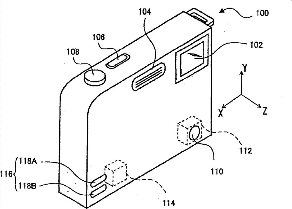
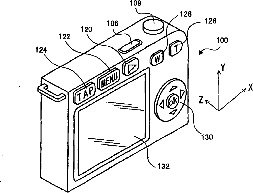
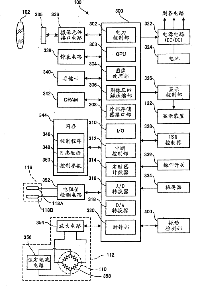
A photographic device
A photographic device and photographic mode technology, applied to TVs, parts of color TVs, parts of TV systems, etc., can solve problems such as instability, inability to suppress wasteful consumption of batteries, and maintain power-saving state, so as to improve operability , Inhibition of waste power consumption, inhibition of recovery effect
- Summary
- Abstract
- Description
- Claims
- Application Information
AI Technical Summary
Problems solved by technology
Method used
Image
Examples
no. 1 Embodiment approach -
[0089] Figure 5A and Figure 5B This is a flowchart illustrating a schematic procedure of processing executed by the CPU 303 in the digital camera 100 according to the first embodiment of the present invention. By being executed by the CPU 303 Figure 5A and Figure 5B The processing procedure shown results in the control schematically shown below.
[0090] (1) When it is not detected that the digital camera 100 is in the water, or the digital camera 100 is not set to a shooting mode suitable for shooting underwater, even if the digital camera 100 is set to the tapping permission mode, the CPU 303 also stops the vibration detection operation in the vibration detection unit 400 when shifting to the standby state. As a result, even if a vibration by a tap operation or a vibration similar to the vibration by a tap operation is applied to the digital camera 100 in the standby state, recovery to the normal operation state is not performed.
[0091] (2) When the digital camera...
no. 2 Embodiment approach -
[0116] Figure 6A and Figure 6B This is a flowchart illustrating a schematic procedure of processing executed by the CPU 303 in the digital camera 100 according to the second embodiment of the present invention. By being executed by the CPU 303 Figure 6A and Figure 6B The processing procedure shown results in the control schematically shown below.
[0117] (1) When the digital camera 100 is not detected to be underwater or is not set to a shooting mode suitable for shooting underwater, when the digital camera 100 is set to the tap operation permission mode When shifting to the standby state, the CPU 303 continues the vibration detection operation in the vibration detection unit 400 . At this time, the CPU 303 sets the vibration detection level to a value (Vref2) higher than the vibration detection level (Vref1) set in the normal operation state. As a result, even when vibrations similar to vibrations caused by tap operations are applied to the digital camera 100 in the...
Embodiment approach 1
[0135] Figure 7A , Figure 7B and Figure 7C This is a flowchart illustrating a schematic procedure of processing executed by the CPU 303 in the digital camera 100 according to the third embodiment of the present invention. By being executed by the CPU 303 Figure 7A to Figure 7C The processing procedure shown results in the control schematically shown below.
[0136] (1) When the digital camera 100 transitions to the standby state while being set in the tap operation permission mode, the vibration detection unit 400 is always allowed to interrupt the operation.
[0137] (2) When the interruption operation of the vibration detection section occurs, the CPU 303 determines whether the digital camera 100 is underwater or is set to a shooting mode suitable for shooting underwater, and if the determination is affirmative, returns to normal operating state.
[0138] (3) When the interrupt operation of the vibration detection section 400 occurs, the CPU 303 determines whether t...
PUM
 Abstract
Description
Claims
Application Information
 - R&D Engineer
- R&D Manager
- IP Professional
- Industry Leading Data Capabilities
- Powerful AI technology
- Patent DNA Extraction
Browse by: Latest US Patents, China's latest patents, Technical Efficacy Thesaurus, Application Domain, Technology Topic, Popular Technical Reports.
© 2024 PatSnap. All rights reserved.Legal|Privacy policy|Modern Slavery Act Transparency Statement|Sitemap|About US| Contact US: help@patsnap.com


