
Power converter with hysteretic control

A converter, DC converter technology, applied in the output power conversion device, the conversion of DC power input to DC power output, the control/regulation system, etc., can solve the problems of complex control and so on

Inactive Publication Date: 2009-09-30
FAIRCHILD SEMICON CORP
View PDF0 Cites 25 Cited by
  • Summary
  • Abstract
  • Description
  • Claims
  • Application Information

AI Technical Summary

Problems solved by technology

The disadvantage of this previously developed design is that it requires an additional error amplifier, making it more complex to implement hysteretic control

Method used


Image

  • Power converter with hysteretic control
  • Power converter with hysteretic control
  • Power converter with hysteretic control

Examples


Embodiment Construction

[0024] Embodiments of the invention and their advantages are found in Figures 1 to 9 Can be very good understanding. The same reference numerals are used to designate like and corresponding parts in the various drawings.

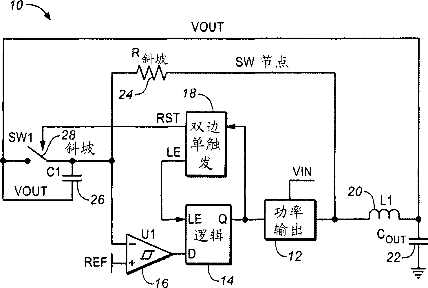
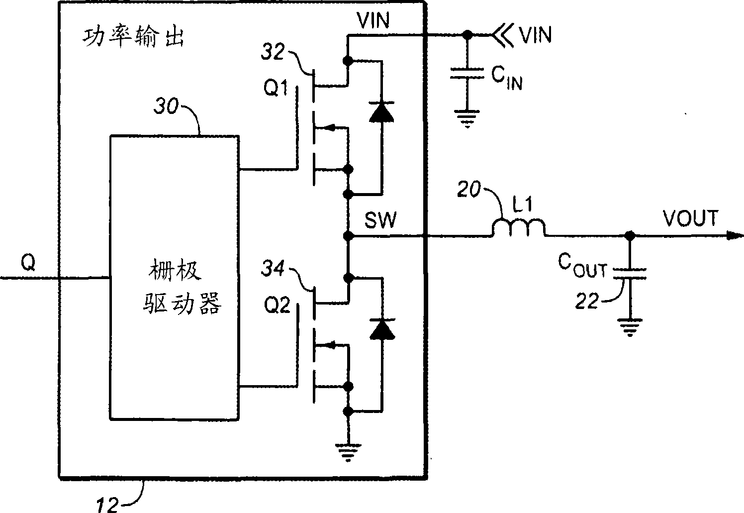
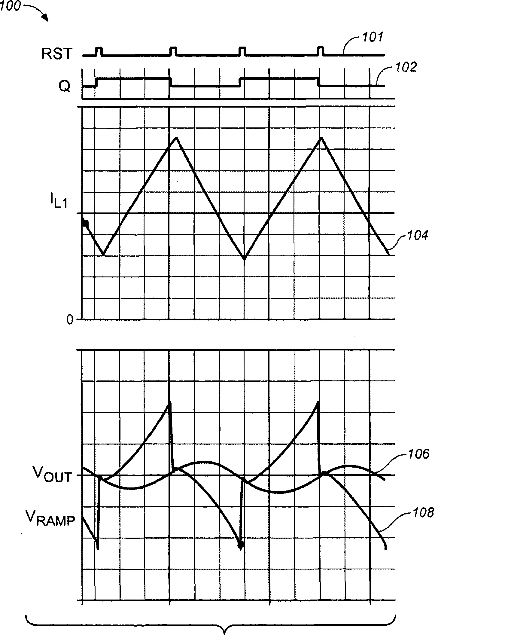
[0025] figure 1 is an implementation schematic diagram of a power converter system 10 according to an embodiment of the present invention. The power converter system 10 may provide direct current (DC) power. The power converter 10 may be used with or included in any electronic device that requires the DC-DC converter described herein. The power converter system 10 receives an input voltage V in and at the output terminal V out provides DC power to the load. As shown, power converter system 10 includes power output circuit 12 , logic circuit 14 , hysteretic comparator 16 , bilateral one-shot circuit 18 , inductor 20 , output capacitor 22 , ramp resistor 24 , capacitor 26 and switch 28 .

[0026] Inductor 20 is coupled to output capacitor 22 at the out...


PUM


Abstract

According to an embodiment of the present invention, a method is provided for hysteretic control of a DC-to-DC power converter system having first and second switches connected in a half-bridge arrangement at a common node and through an inductor to a regulated output terminal, wherein the regulated output terminal is connectable to an output capacitor and a load. The method includes the following: generating a feedback signal which tracks current flowing through the inductor; comparing the feedback signal against a reference voltage to general a control signal; and controlling the magnitude of an output voltage which appears at the regulated output terminal in response to the control signal, thereby providing hysteretic control of the DC-to-DC converter which is not dependent on an equivalent series resistance (ESR) of the output capacitor.

Description

technical field [0001] The present application relates to power converters, and more particularly, to power converters with hysteretic control. Background technique [0002] Power converters are fundamental to many modern electronic devices. Among other capabilities, the power converter can regulate the voltage level down (buck converter) or up (boost converter). Power converters can also convert from alternating current (AC) power to direct current (DC) power and vice versa. Typically, a power converter may be implemented with one or more switching devices, such as transistors, that can be switched on and off to deliver power to the output of the converter. A power converter may also include one or more capacitors or inductors. [0003] In some applications of power converters, the load current can vary widely (eg, over multiple orders of magnitude), in which case a fast response in regulation or control is required. One form of regulating a power converter is hystereti...

Claims


Application Information

Patent Timeline
Patent Type & Authority Applications(China)
IPC IPC(8): G05F1/00
CPCH02M3/157H02M3/158
Inventor J·克莱恩
Owner FAIRCHILD SEMICON CORP
Learn More