
Medical cutting tool

A cutting tool and medical technology, applied in the field of bone resection collection tools, can solve the problem that cutting tools cannot perform stable perforation, and achieve the effects of accelerating regeneration and inhibiting damage

Active Publication Date: 2012-12-05
WAKAYOSHI SEISAKUSHO
View PDF10 Cites 0 Cited by
  • Summary
  • Abstract
  • Description
  • Claims
  • Application Information

AI Technical Summary

Problems solved by technology

[0020] The guide members described in Patent Documents 8 and 9 use slit-shaped grooves formed in the vertical direction to guide the cutting tool. However, when such a groove is used as a guide surface, the cutting tool can be inserted from the lateral direction and positioned easily. , on the contrary, there is a disadvantage that the cutting tool is easy to swing in the groove during the piercing action, and stable piercing action cannot be performed.

Method used


Image

  • Medical cutting tool
  • Medical cutting tool
  • Medical cutting tool

Examples


Embodiment Construction

[0071] Hereinafter, embodiments of the present invention will be described in detail. In addition, the embodiments described below are the best specific examples for implementing the present invention, so there are no technical limitations. However, as long as there is no intention to limit the present invention in the following descriptions, the present invention is not limited. in these ways.

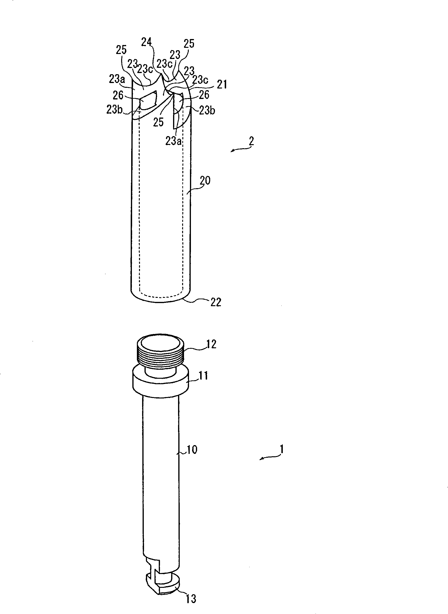
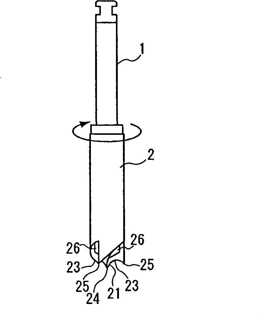
[0072] figure 1 It is an exploded perspective view related to the medical cutting tool of the present invention. The medical cutting tool includes a support member 1 and a cutting member 2 . In the support member 1 , a flange portion 11 and a screw fixing portion 12 are formed on one end side of a rod-shaped main body portion 10 , and a locking portion 13 is formed on the other end side. In the cutting member 2 , a cutting portion 21 is formed at one end of a cylindrical body portion 20 , and a mounting screw portion 22 is formed at the other end.

[0073] The mounting screw port...


PUM


Abstract

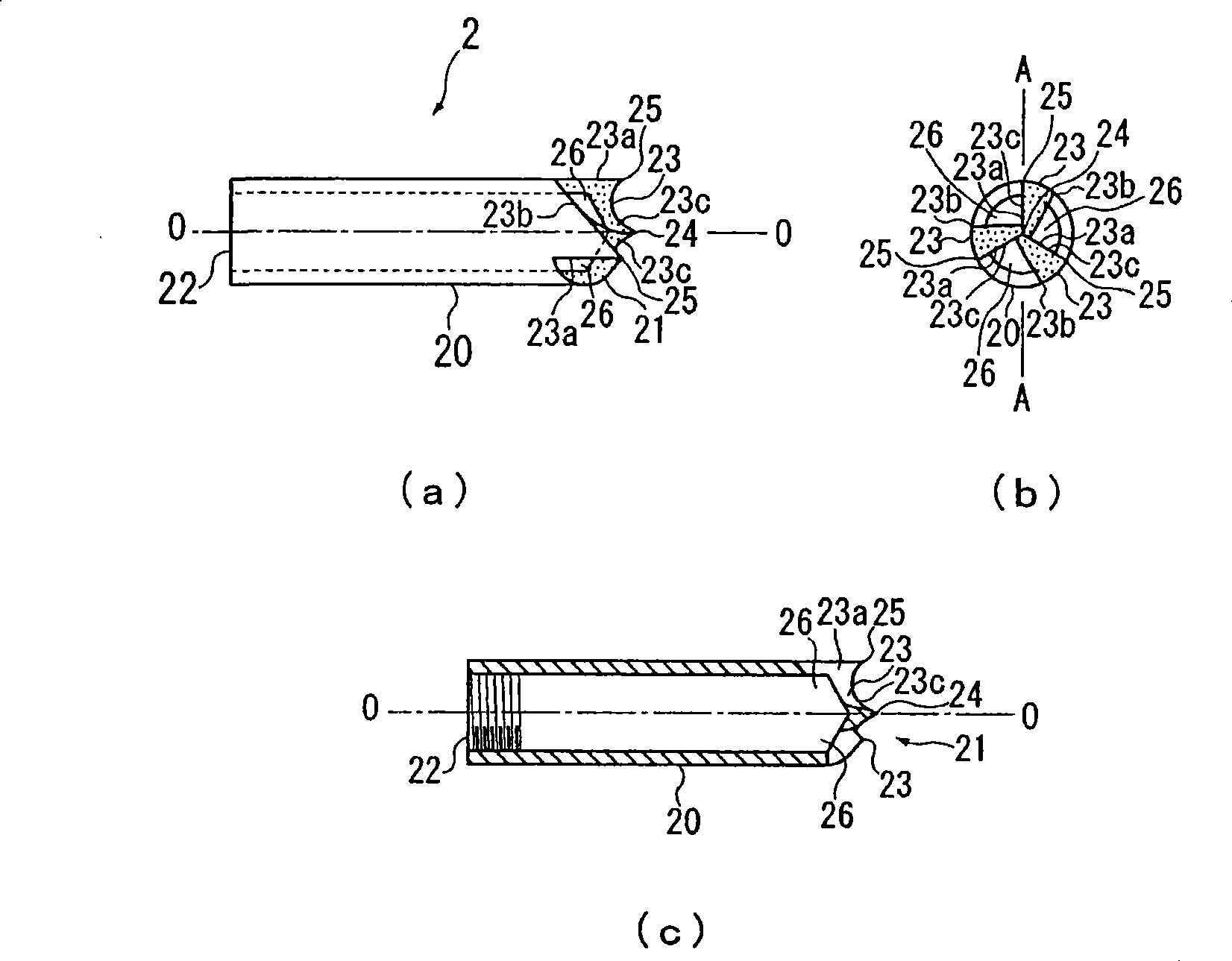
Intended is to provide a medical cutting tool, which can recover chips produced by the cutting action, thereby to form a hole for inserting an implant stably therethrough. The medical cutting tool comprises a supporting member (1) and a cutting member (2). This cutting member (2) has a cutting portion (21) formed at one end portion of a cylindrical body portion (20), and the cutting portion (21) has cutting edges (23) extended radially from the center axis of the body portion (20) toward the outer circumference. A center tip portion (24) is formed at the central portion, in which the cutting edges (23) are formed, and outer circumference tip portions (25) are formed at the outer circumference end portion. Between the cutting edges (23), inclined side faces (23b) and side faces (23a) of the adjoining cutting edges (23) are formed to intersect in valley shapes, in which inlet portions (26) are so individually formed in the valley-shaped portions as to communicate with the inside of the body portion (20).

Description

technical field [0001] The present invention relates to a medical cutting tool, a guide member and a bone harvesting tool used in dental, oral surgery, orthopedic surgery to perforate a bone to form an insertion hole for transplantation. Background technique [0002] In dental, oral surgery, plastic surgery and other surgical operations, implants such as artificial tooth roots, artificial joints, artificial bones, and fracture treatment tools must be inserted accurately, so as to perforate and form insertion holes in the living bones of the human body in advance. , inserting the implant into the insertion hole for positioning and fixing. [0003] As a medical cutting tool used in this kind of piercing, for example, Patent Document 1 describes a medical hollow drill, which penetrates in the axial direction to form a discharge path for cutting chips generated during the cutting operation, and separates them at regular intervals. A plurality of cutting edges are radially forme...

Claims


Application Information

Patent Timeline
Patent Type & Authority Patents(China)
IPC IPC(8): A61B17/16A61C3/02A61C8/00
Inventor 若吉修似
Owner WAKAYOSHI SEISAKUSHO
Learn More